Do you have a question about the andrews 40/61 and is the answer not in the manual?
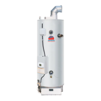
General overview of the water heater's design and installation requirements.
Outlines safety regulations applicable to the heater's use and installation.
Provides technical specifications for the Standard Range models.
Provides technical specifications for the Hi-Flo Range models.
Legal requirements and overview of installation procedures.
Guidance on selecting a suitable installation location for the heater.
Details requirements and procedures for connecting the gas supply.
Recommendations and requirements for flue installation.
Specifies requirements for air supply and ventilation for safe operation.
Discusses water quality, scale formation, and treatment recommendations.
Explains the Hydrojet system for cold water inlet.
Details water connections for standard range vented systems.
Details water connections for standard range unvented systems.
Details water connections for Hi-Flo range vented systems.
Details water connections for Hi-Flo range unvented systems.
Commissioning steps for Standard Range permanent pilot models.
Commissioning steps for Hi-Flo Range auto ignition models.
Guidance for the user on operation and maintenance.
Safety precautions for the user regarding lighting and operation.
Operating sequence for Standard Range models.
Operating sequence for Hi-Flo Range permanent pilot models.
Explanation of the Energy Cut-Off safety feature.
General guidance on servicing procedures and frequency.
Steps for checking and cleaning the burner assembly on Standard Range models.
Checking and cleaning flue ways for Standard Range models.
Inspection and replacement of magnesium anodes.
Procedure for replacing the gas control valve.
Replacing the thermopile, pilot burner, and restrictor.
Troubleshooting common faults for permanent pilot models.
Troubleshooting common faults applicable to all models.
Parts list and illustrations for specific Standard Range models.
Parts list and illustrations for the Hi-Flo Model 32/143.
Illustrations of the Unvented Systems Kit for Standard Range.
Lists the technical specifications of the control system.
Describes the step-by-step operational sequence of the control system.
Guides users through troubleshooting common water heater faults.
Procedure for accessing service mode for diagnostics and settings.
Definitions for various error codes displayed by the control system.
Detailed procedure for testing the thermostat circuit.
Steps and table for testing sensor resistance at various temperatures.
Procedure for testing pilot operation and diagnosing faults.
Procedure for testing main burner operation and diagnosing faults.
Steps for removing and inspecting the main burner and pilot.
Steps for removing and inspecting anode rods.
| Brand | andrews |
|---|---|
| Model | 40/61 |
| Category | Water Heater |
| Language | English |