4. Execute DLSCC 2 to set Call Processing Parameter – Carrier Aggregation – Number of DL SCC to 2.
5. Execute DLCHAN 300 to set Common Parameter - Frequency - DL Channel to 300 simultaneously with UL
Channel to 18300.
6. Execute DLCHAN_SCC1 50665 to set Common Parameter - SCC-1 - DL Channel to 50665.
7. Execute DLCHAN_SCC2 50863 to set Common Parameter - SCC-2 - DL Channel to 50863.
8. Execute BANDWIDTH 20MHZ to set Common Parameter - Channel Bandwidth to 20 MHz.
9. Execute BANDWIDTH_SCC1 20MHZ to set Common Parameter - SCC-1 - Channel Bandwidth to 20 MHz.
10. Execute BANDWIDTH_SCC2 20MHZ to set Common Parameter - SCC-2 - Channel Bandwidth to 20 MHz.
11. Execute LAA_SCC1 LAA to set Common Parameter - SCC-1 - LAA mode to LAA.
12. Execute LAA_SCC2 LAA to set Common Parameter - SCC-2 - LAA mode to LAA.
13. Execute DLIMCS_PARTIALSF_SCC1 5 to set Common Parameter - SCC-1 - MCS Index (Partial Subframe) to
5.
14. Execute DLIMCS_PARTIALSF_SCC2 5 to set Common Parameter - SCC-2 - MCS Index (Partial Subframe) to
5.
15. Execute LAAPAT USER to set Call Processing Parameter – Carrier Aggregation – LAA Scheduling Pattern
to User Define.
16. Execute LAACYCLE 10 to set Call Processing Parameter – Carrier Aggregation – LAA Cycle to 10.
17. Execute LAAONDURATION 10 to set Call Processing Parameter – Carrier Aggregation – LAA On Duration
to 10.
18. Execute LAALASTSYMBOL 14 to set Call Processing Parameter – Carrier Aggregation – LAA Last Symbol
to 14.
19. Execute DMTCPERIOD MS40 to set Call Processing Parameter – Carrier Aggregation – DMTC Periodicity
to ms40.
Location Registration 12.1.2.
This performs UE location registration after setting the initial conditions (12.1.1).
Refer to chapter 2.3.4.
Test Mode Connection and Disconnection 12.1.3.
Refer to chapter 2.3.5.
Flexible Transmission Scheduling Setting 12.2.
At this setting, the DL signal is not transmitted on some subframes and some symbols in the partial subframe.
Initial Condition Setting 12.2.1.
The initial conditions must be set before measurement.
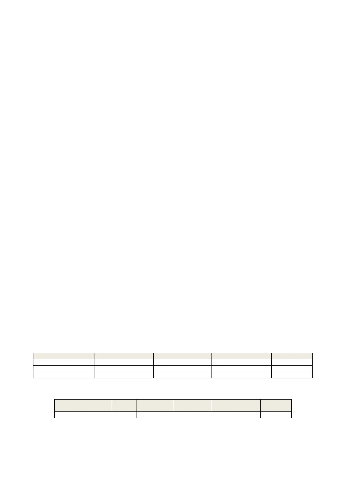
A setting example for 3CA (FDD/LAA/LAA) at each condition is shown in the following table
The LAA DL Signal settings are shown below.
(*) The LAA Start Subframe is fixed to 0 when LAA Scheduling Pattern is User Define.
366
 Loading...


