Do you have a question about the Anritsu ML2400A Series and is the answer not in the manual?
Describes symbols found on equipment and in manuals, like prohibited, compulsory, warning/caution, and note symbols.
Explains safe handling and care for exposed sensor connectors to prevent damage.
Outlines the power sources (AC, DC, battery) and requirements for operating the ML2400A Series Power Meter.
Illustrates and describes the front panel connectors, including the calibrator and sensor connections.
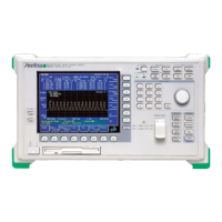
Details the front panel controls, including the graphic LCD, numeric keypad, power controls, soft keys, and menu keys.
Explains the controls for sensor data processing, including setup, settle percentage, and mode selection.
Details how to control the operation of display channels, including setup, input configuration, units, and resolution.
Explains how to define measurement conditions and time periods for the ML2400A.
Covers system controls for operating modes, display visibility, sound, rear panel functions, and battery state.
Lists GPIB commands for programming the ML2400A Series Power Meter in ML24XXA (native) mode.
Describes how the ML2400 Anritsu power meter emulates the GPIB communication of other power meters.
Provides an alphabetical listing of GPIB commands for programming the ML2400A Series Power Meter in ML4803A mode.
Lists GPIB commands for programming the ML2400A Series Power Meter in HP 436A emulation mode.
Lists GPIB commands for programming the ML2400A Series Power Meter in HP 437B emulation mode.
Lists GPIB commands for programming the ML2400A Series Power Meter in HP 438A emulation mode.
Offers general guidelines and examples for programming the ML2400A Series Power Meters using GPIB commands in Visual Basic or C.
Presents controls for sensor data processing, including setup, settle percentage, and mode selection.
Details control over display channel operation, including setup, input configuration, units, and resolution.
Explains trigger setup menus available in Profile, Readout, and Power vs. Time modes.
Covers system controls for operating modes, display visibility, sound, rear panel functions, and battery state.
Establishes the 0.0 dBm reference calibration and zeroing of sensors.
| Brand | Anritsu |
|---|---|
| Model | ML2400A Series |
| Category | Measuring Instruments |
| Language | English |






 Loading...