Do you have a question about the Anritsu ML2437A and is the answer not in the manual?
Provides installation and operational information for the ML2437A and ML2438A Power Meters.
Information on downloading updated software and related literature from the product page library.
Details on the ML243xA ID number affixed to the rear panel for ordering parts.
Lists the available ML243xA Power Meters with their sensor inputs and included cables.
References the Technical Data Sheet for a complete listing of options, accessories, and power sensors.
Procedure for inspecting the shipping container and instrument for damage.
Guidelines for handling the power meter sensors, referring to the sensor manual for connector care.
Details on AC line, DC, and battery power requirements for the ML243xA Power Meter.
Specifications for operating temperature and humidity, and recommendations for optimal battery life.
Information on mounting the ML243xA into a standard 48 cm equipment rack with available option kits.
Instructions for handling the optional battery pack, including charging, removal, and replacement procedures.
Procedures for preparing the power meter for storage and shipment, including environmental requirements.
Step-by-step instructions for packing the ML243xA for return shipment to Anritsu.
Overview of the three types of memory devices in the ML2437A/38A Power Meters.
Information on using secure mode to wipe non-volatile static RAM and reset to factory defaults.
Procedure to permanently erase all user data, including saved set-up data.
Details on EEPROM contents in Anritsu Power Sensors and how to clear user cal factor table data.
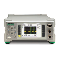
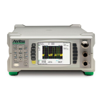
Illustrations and descriptions of the ML243xA's front panel connectors.
Detailed explanation of the rear panel connectors and their functions.
Detailed explanations of the front panel controls, including numeric keypad, LCD, soft keys, and power button.
Description of the power-on self test (POST) and how errors or warnings are displayed.
Controls for sensor data processing, including Setup, SENSOR, OPTION, MODE, HOLD, and Calfactor.
Controls the operation of display channels, including setup, input, units, resolution, and min/max tracking.
Defines conditions and time periods for measurements, including SOURCE, DELAY, WIDTH, and EDGE.
Controls operating modes, display visibility, sound, rear panel functions, and battery state.
Establishes the 0.0 dBm reference calibration and zeroing of sensors.
Step-by-step guide to performing a power measurement, including sensor connection and zeroing.
Procedure to zero the sensor to remove DC offset and minimize measurement noise floor.
Recommendation to reference power sensors to the ML243xA 50 MHz, 0.0 dBm calibrator.
Function that completes both zeroing and calibration operations in sequence.
How to verify the performance of individual signal channel inputs using an Anritsu Range Calibrator.
Instructions for connecting a parallel printer to the ML243xA's rear panel port.
Operating the ML243xA remotely via GPIB connection to a host computer/controller.
Operating the ML243xA remotely through the rear panel serial connector.
Operating the ML243xA remotely via a modem connected to the rear panel serial connector.
Describes setting up and viewing signals in Profile mode, allowing graphical signal analysis.
Allows synchronization to an RF source for swept power-accurate measurements.
Provides a graphical chart display of channel readings over a user-defined period.
Explains how to define and store calibration factor sets in the sensor's EEPROM.
Information on achieving the fastest readings from the ML243xA when operating under GPIB control.
Details on software loader instructions for firmware updates.
Guide to making standard carrier wave power measurements, including switching on and presets.
Correctly measuring amplitude modulated carriers with average powers greater than -25 dBm.
Techniques for minimizing noise and improving readings at low power levels, including averaging modes.
Demonstrates measuring power on two channels simultaneously for various applications.
Utilizing the dual input ML2438A for simultaneous measurements with two sensors.
Measuring the 1 dB compression point of an amplifier using a two-input power meter setup.
Measuring pulse output power by entering the pulse duty cycle for mathematical correction.
Viewing signals graphically and digitally, including setting up triggering for pulse analysis.
Measuring GSM-TDMA bursts within an eight-slot frame using profile and trigger settings.
Taking power measurements over a user-defined period and logging the data.
Measuring power against swept frequency to perform a frequency response measurement.
Explains the format for native and HP emulation GPIB commands, including data delimiters and numeric suffixes.
Details on equivalent query commands that return current values or settings.
Recommended GPIB driver configuration for reliable communication with the ML243xA.
Explains IEEE 488.1 level commands such as Device Clear, Device Trigger, and Goto Local.
Fundamentals of IEEE 488.2 GPIB operation and its implementation in the ML243xA Power Meter.
Basic format for 488.2 commands, including mnemonics, parameters, and terminators.
Categorization of commands into functional groups like BNC, Calibration, Channel, and GPIB Setup.
Alphabetical listing of GPIB commands used to program the ML243xA in its native mode.
Details on emulating other power meters' GPIB communication, including command restrictions.
Alphabetical listing of GPIB commands for ML4803A emulation mode.
Alphabetical listing of GPIB commands for HP436A emulation mode.
Alphabetical listing of GPIB commands for HP437B emulation mode.
Alphabetical listing of GPIB commands for HP438A emulation mode, supporting HP437B cal factor commands.
Visual Basic or C language example for retrieving readings via GPIB.
Example function to retrieve graph display setup and data from the ML2430A.
Demonstrates using Status Registers for synchronization and making readings.
Function using status registers to synchronize GPIB commands and return data.
Program example to decode binary output messages like OGBD, MXGDB, MNGDB, OFFTBR, CFURD.
Information on obtaining technical support and details to provide.
Lists system configurations, rear panel inputs/outputs, and GPIB interface details.
Details default parameters loaded when 'preset' is selected, covering sensor, channel, and trigger setups.
Details front panel error messages, their meanings, and how to contact support.
Lists specific error messages related to calibration and zeroing operations.
Reference tables for ML24XXA native mode commands, sorted by functional group.
Reference tables for ML4803A emulation mode commands.
Reference tables for HP436A emulation mode commands.
Reference tables for HP437B emulation mode commands.
Reference tables for HP438A emulation mode commands.
Lists HP-IB commands for HP437B and HP438A, and their support status on ML243xA.
Precautions regarding connector pin depth to prevent damage and ensure compatibility.
Guidelines for proper connector torque to avoid damage and ensure good connection.
Precautions regarding mechanical shock to maintain the service life of precision connectors.
Instructions for cleaning connector interfaces using isopropyl alcohol and cotton swabs.
| Brand | Anritsu |
|---|---|
| Model | ML2437A |
| Category | Measuring Instruments |
| Language | English |

