Example 2: Measuring Modulated Carrier Measurement Examples
7-8 PN: 10585-00001 Rev. P ML2437A/38A OM/PM
7-2 Example 2: Measuring Modulated Carrier
The Anritsu power sensors MA2440A and MA2470A are fast responding diode sensors. When
measuring signals with an average power greater than –25 dBm and an amplitude
modulation component, all diode sensors will normally give incorrect measurement results.
This is because the diode is not detecting in its square law region.
A special feature of the Anritsu diode sensors and power meters is the ability to correctly
measure amplitude modulated carriers with average powers greater than
–25 dBm. This is possible because the diodes are fast responding and have a large video
bandwidth. This means they demodulate signals that are within this bandwidth.
This property is used in the modulation average mode to give accurate average power
readings at high power levels with modulated signals.
Modulation average is not required when making measurements with thermal sensors.
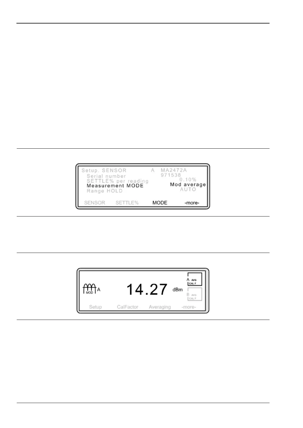
To change the measurement mode, press [Sensor]
> [Setup] > [MODE].
The Measurement screen will now display a stable reading. A modulation icon reminds you
that this mode is active.
Figure 7-13.
Figure 7-14.