Measurement Examples Example 6: Gain Compression Measurement
ML2437A/38A OM/PM PN: 10585-00001 Rev. P 7-15
7-6 Example 6: Gain Compression Measurement
A common application for a two input power meter is for gain compression measurements on
amplifiers. In this example, we will measure the 1 dB compression point for an amplifier with
20 dB gain.
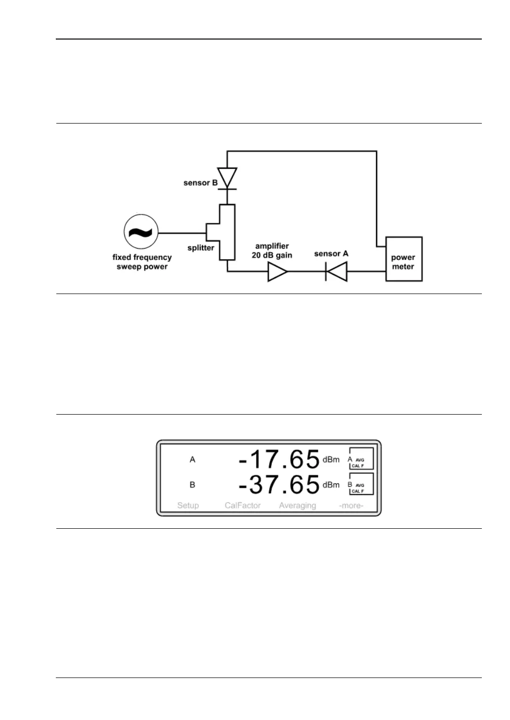
Connect your measurement system as shown above. Allocate sensor A to channel 1 and
sensor B to channel 2 (see Example 4 and 5) The signal source should be set to a suitable CW
frequency to test the amplifier. Follow the procedures described in Example 1 to zero and
calibrate the sensor and to enter the correct calibrator factor frequency for this measurement.
The source power level should initially be set to a power at which the amplifier is on its
linear, small signal gain region. In this case, -30 dBm. Your measurement screen may look
something like this:
A is displaying the output power of the amplifier. B is displaying the input power to the
amplifier. (Note a signal splitter has a nominal path loss of 6 dB.)
We can display the gain of the amplifier directly if we set channel 1 to A/B (see Example 4).
Press [Channel]
> [Setup] > [Input].
Figure 7-22.
Figure 7-23.