Serial Remote Operation Procedures
6-4 PN: 10585-00001 Rev. P ML2437A/38A OM/PM
6-8 Serial Remote Operation
The ML243xA Power Meter can be operated remotely through the rear panel serial connector
(See Chapter 3, Connectors, for the location of the serial connector). Whereas GPIB has
restrictions on total cable length and cable length between instruments, RS232 serial
communication is not as limited. The GPIB can also be prone to electrical interference and is
not easily electrically isolated, while RS232 can be isolated using optical couplers. Serial
interface remote operation can be useful if the testing is to be done in the presence of high
electrical fields and like environments.
While most standard serial cables will suffice, a 9-pin null-modem serial interface cable is
available from Anritsu as an optional accessory (part number 2000-1544). Note that the
hardware handshake CTS and RTS lines are used to control the flow of data in and out of the
power meter and must be available in the cable as hardware handshaking is always enabled.
The DTR and DSR lines are connected together within the meter.
The serial interface baud rate can be set using the System > Rear panel > RS232 menu
selection or the RSBAUD command. Available baud rates are: 1200, 2400, 4800, 9600
(default), 19200, and 38400. Other parameters are predefined as: 8 bits, no parity and 1 stop
bit and cannot be changed.
Commands are entered as with the GPIB interface, conforming to the command format for
the operation (emulation) mode selected. All GPIB commands are supported. There are some
additional commands, specific to the serial interface, that are prefixed with an exclamation
mark (!). In the emulation modes, when running under GPIB, the measured data is always
available when the meter has been addressed to talk. In serial mode, the meter cannot be
addressed to talk, but measurement data can still be obtained by using the GPIB trigger
commands TR1 and TR2 in the HP437 and HP438 emulation modes, and T and I in the
HP436 emulation mode.
All GPIB type commands and command strings should be terminated with a new line
character (0A hex). The special serial mode commands do NOT require a termination
character.
Note
Serial interface remote operation is not available when the ML243xA Series Power
Meter is operating from the internal battery.
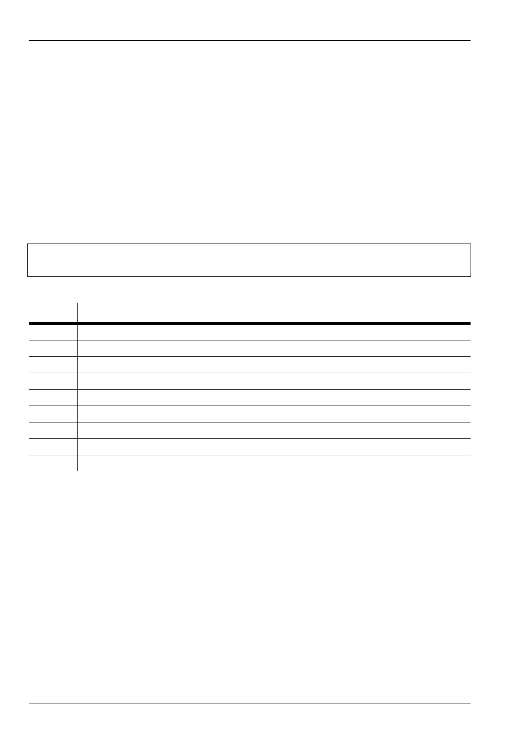
Table 6-1. ML243xA Power Meter Serial Connector Pinouts
PIN SIGNAL
1 NOT USED
2 RX data
3 TX data
4 DTR handshake signal
5 signal ground
6 DSR handshake signal
7 RTS handshake signal
8 CTS handshake signal
9 NOT USED