ML2437A/38A OM/PM PN: 10585-00001 Rev. P 7-1
Chapter 7 — Measurement Examples
7-1 Example 1: Standard CW Power Measurements
This first example will explain everything you need to know about the ML2430A Series Power
Meter when making standard carrier wave power measurements. However, the power meter
is capable of much more and examples 2 to 11 explore its functionality in greater depth.
1. Switching on
Turn the ML2430A on using the front panel ON/OFF button.
2. Preset the meter to a known state
A Preset returns the ML2430A to its default settings. It is recommended that this is
carried out before each new measurement type and whenever the meter is reconfigured
for a new measurement. To preset, press [System]
> [Setup] > [-more-] > [PRESET] >
[Factory]
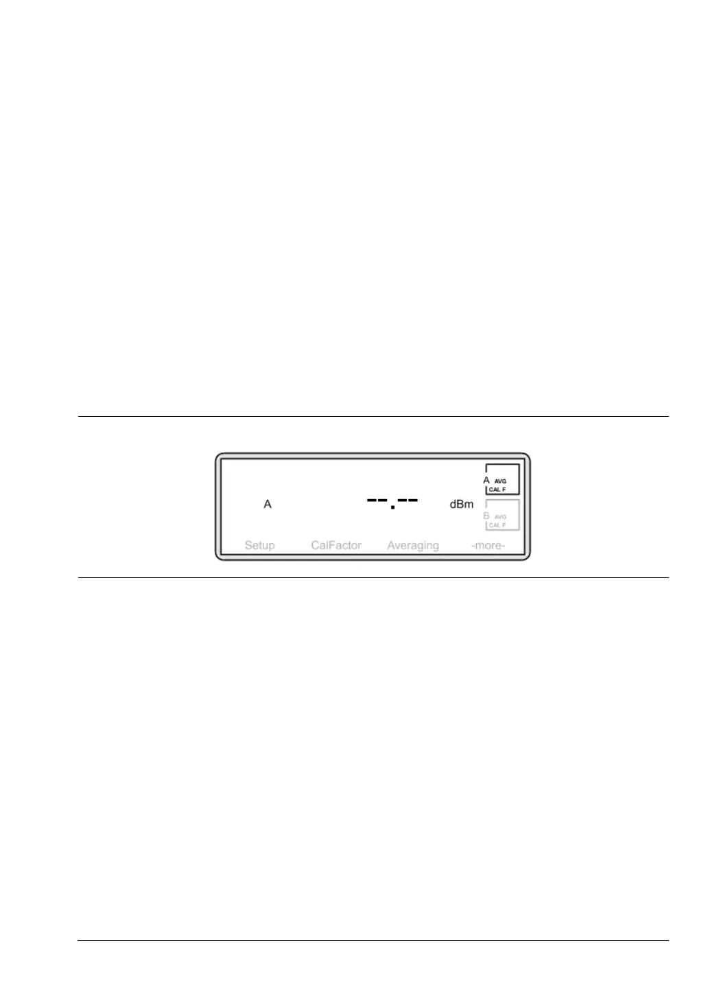
Having performed a Preset, the Measurement screen is displayed:
Select the correct power sensor for your measurement. Consider points such as power
range, frequency range, connector type, and speed of response required.
See the appendix for a table of power sensor model numbers, power and frequency
ranges.
3. Zero the sensor
Zeroing the power sensor removes any residual DC offset on the sensor/meter
combination. After a zero the measurement noise floor is minimized. It is recommended
that you always zero the sensor at the beginning of each measurement session and
prior to taking important power readings in the bottom
20 dB of its dynamic range.
Anritsu recommends that during Zeroing, the sensor is connected to the device under
test having ensured it is not emitting any power (see 5. Connections). If this is not
possible, then the sensor should be zeroed to the CALIBRATOR socket on the ML2430A
front panel. The third option would be to Zero with the sensor in free space i.e. not
connected to anything.
Press [Cal/Zero]
> [Zero]
Figure 7-1. Measurement Screen