Example 1: Standard CW Power Measurements Measurement Examples
7-2 PN: 10585-00001 Rev. P ML2437A/38A OM/PM
The ML2430A will take a few seconds to perform the Zero and will beep when finished.
The Measurement screen is displayed and returns a value of approximately -75 dBm
for a standard diode sensor or –40 dBm for a thermal sensor.
4. Calibration
At the beginning of a measurement session, it is good practice to calibrate the sensor.
Connect the sensor to the CALIBRATOR connector on the ML2430A front panel and
press [Cal/Zero]
> [-Cal 0 dBm].
The ML2430A will take a few seconds to perform the calibration and will beep when
finished.
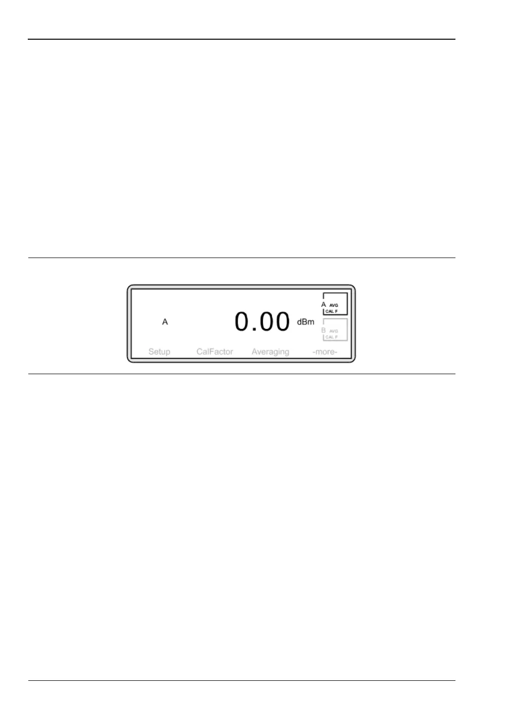
To validate that the meter is working correctly, you may choose to now measure the 0
dB calibration signal. Press [Cal/Zero]
> [-more-].
Check that the left-hand soft key reads RF ON. If it reads RF OFF, press
[RF ON] to toggle the setting to RF ON. A correctly functioning instrument will return
the following screen:
5. Connections
Connect the power meter to the device under test via the sensor. Ensure:
• you are using the appropriate sensor for the measurement you wish to make
• the sensor is fitted with the correct connector for the device you wish to test.
See the appendix for a table of power sensor model numbers, power and frequency
ranges.
Anritsu do not recommend the use of adapters between the power source and the sensor
since this can introduce measurement errors.
6. Applying a calibration factor
The accuracy of a measurement is affected by the frequency response of the individual
sensor. To correct for the sensor frequency response you can enter into the meter the
calibration factor for the measurement frequency. This calibration factor data is stored
in an EEPROM in the power sensor body.
Press [Sensor]
> [Cal Factor].
Figure 7-2.