2. System Connections
VectorStar MN469xC QSG PN: 10410-00738 Rev. C QSG-3
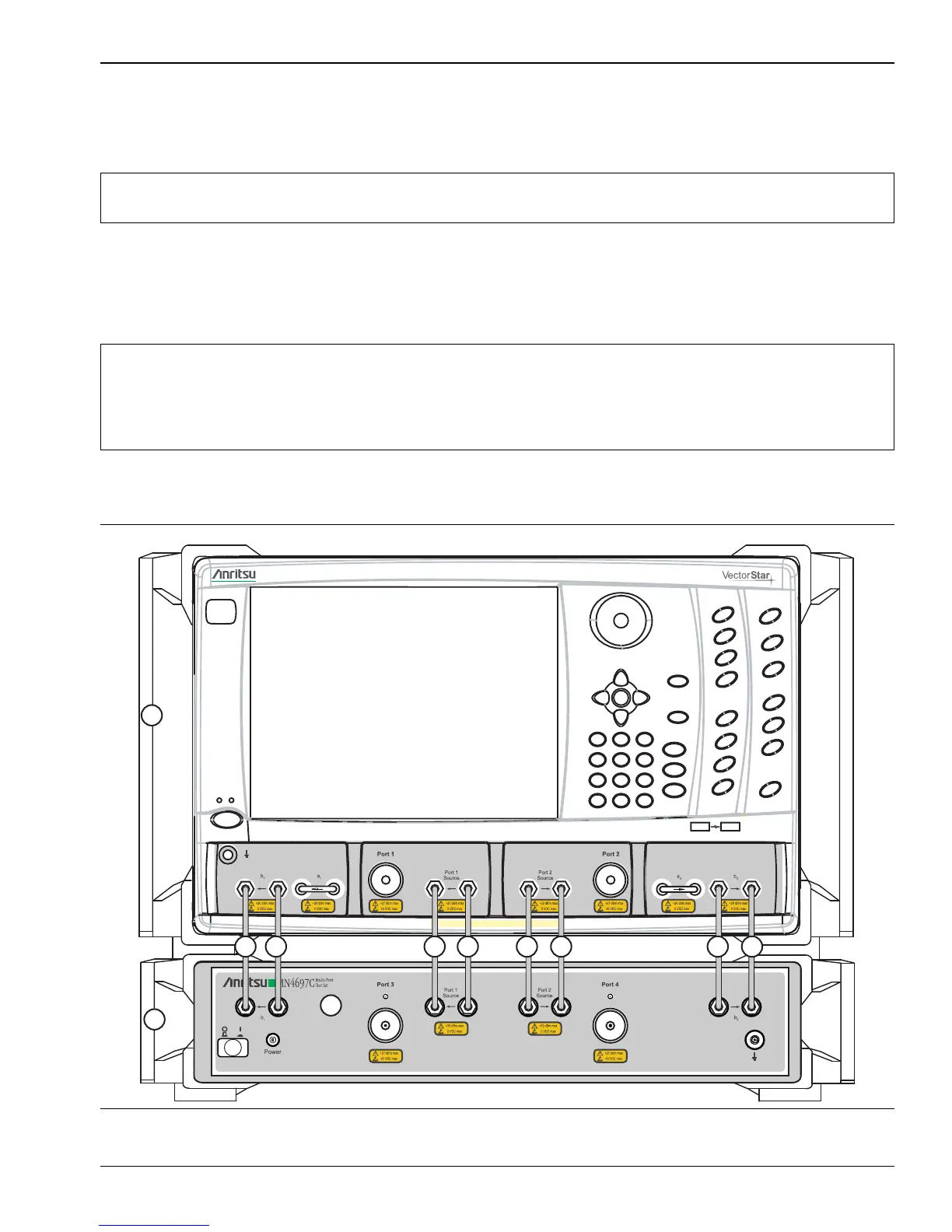
2. System Connections
The figure below shows the front panel connections between the Test Set and VNA. Make the semi-rigid cable
connections as shown in Figure 1, Figure 2, and in Table 1.
Front Panel Connections
1. Place the VNA on top of the Test Set as shown in Figure 1.
2. Disconnect the front panel RF cable loops from ports that will be connected to the test set.
3. Use the eight provided RF (K or V) male-to-male cables, or other semi-rigid or phase stable male-to-male
RF cables to make the connections as shown in Figure 1 and in Table 1.
Note
Before installing the test set in its operating environment, ensure that the airflow hole pattern at the
right side of the instrument is clear. This is necessary to provide adequate ventilation for the test set.
Note
When front panel loops on a VectorStar MS464xA/B are removed and then reinstalled for any
reason, ensure they are returned to their original locations. If they are reconnected to locations other
than their original, this can affect the VNA factory calibration. If the loop locations are forgotten and
the calibration has been compromised, refer to the VectorStar Maintenance Manual for instructions
on performing a new factory RF calibration.
Figure 1. MS464xA/B VNA and MN469xC Test Set Front Panel Connections

 Loading...


