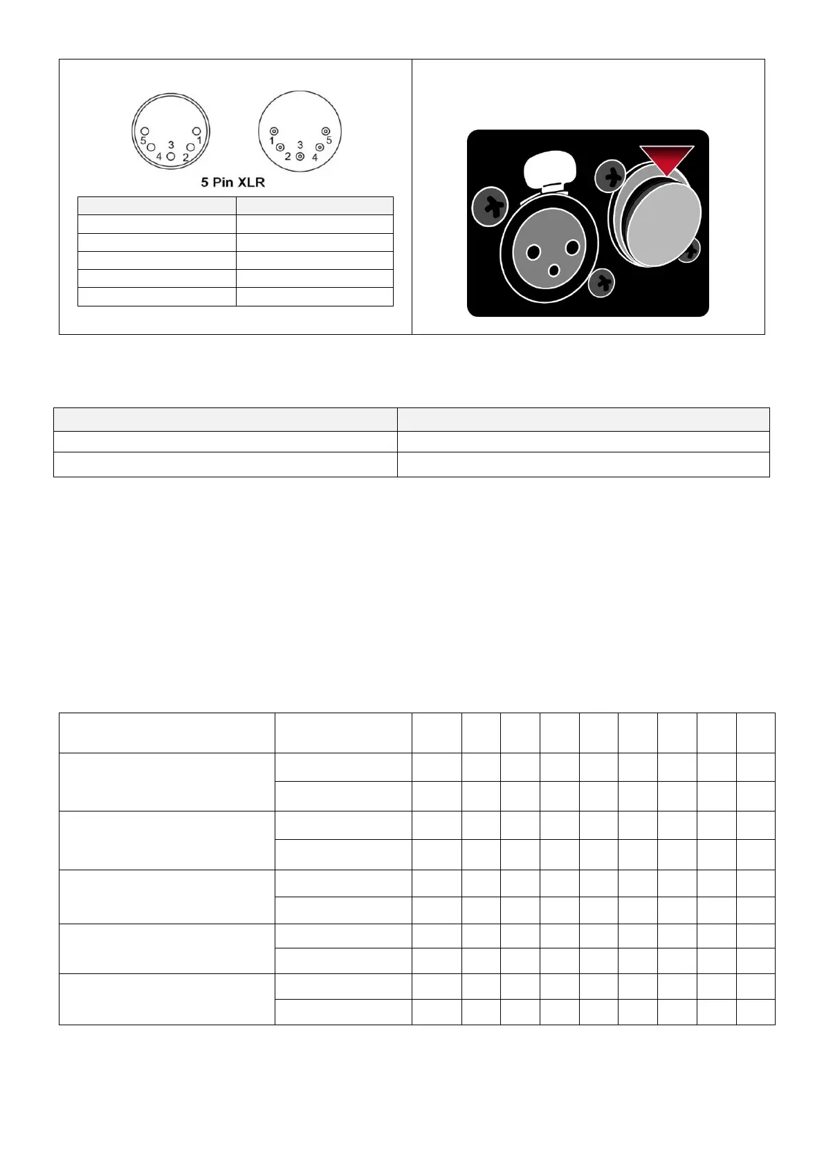
** There is a protection cap on DMX IN, please
remove it with your finger before operation.
10.3 Addressing
Each device occupies 1 channel. To ensure that the control signals are properly directed to each device, they require
addressing. This is to be adjusted for every single device by changing the DIP-switches as set out in the table
below. The starting address is defined as the first channel from which the device will respond to the controller.
Please make sure that you do not have any overlapping channels in order to control each device correctly and
independently from any other fixture on the DMX data link. If two, three or more devices are addressed similarly,
they will work similarly.
Occupation of the DIP-Switches: