ACT-5X+ Exciter User Manual
Version 1.1 5/8/2015 Page 7 of 33
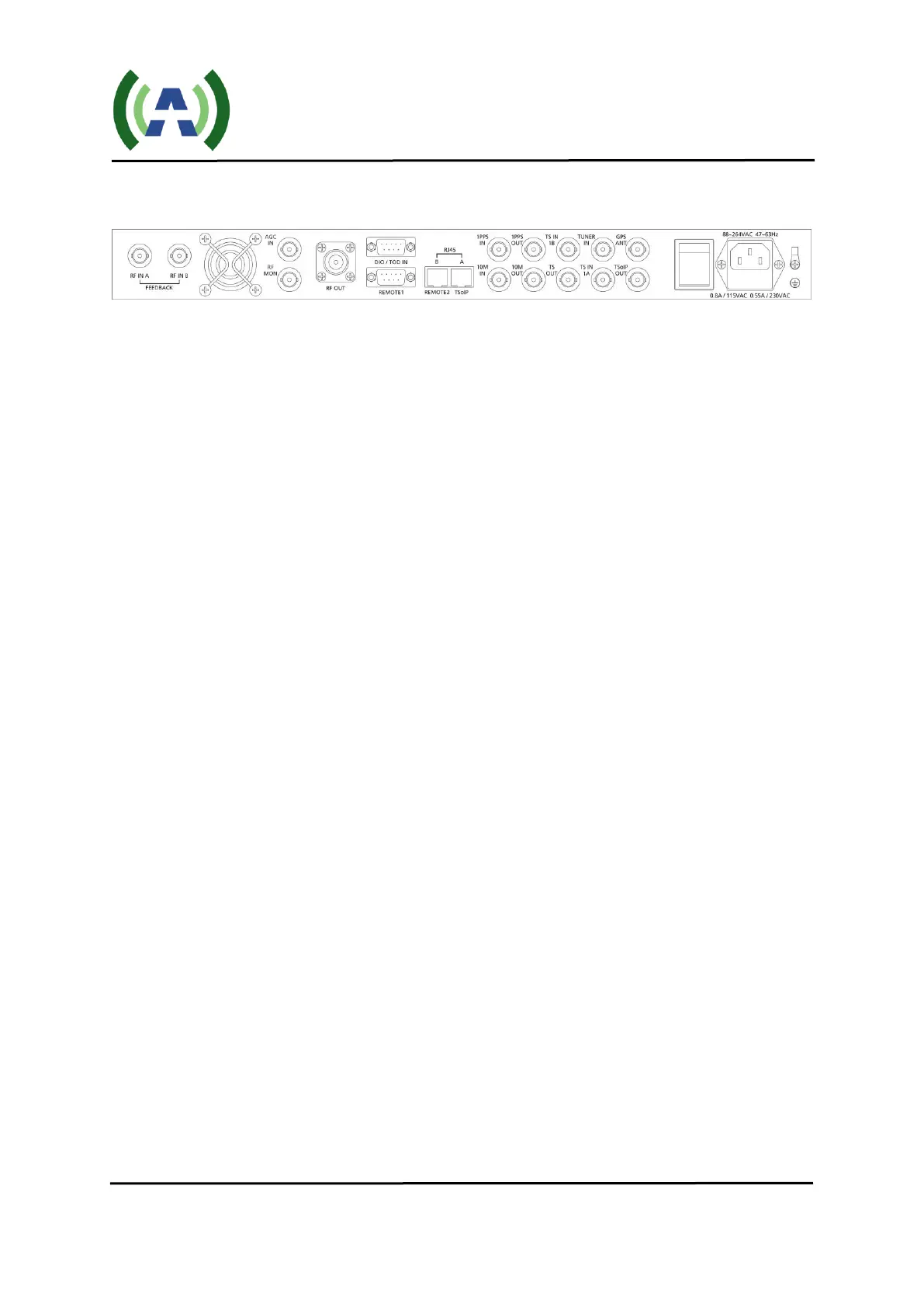
1.2 Back Panel
RF_IN_A: Feedback signal for SNR/IMD displayed and AGC RF feedback option,
sampled after the band-pass filter (-5 to -15dBm)
RF_IN_B: Feedback signal, sampled before the band-pass filter (-5 to -15dBm)
AGC_IN: AGC DC feedback option (0-5VDC)
RF_MON: Loop out of [RF_OUT] for monitoring (10 dB below RF_OUT)
RF_OUT: Main RF signal output (nominal 0 dBm output)
DIO/TOD IN (RS232): Digital IO for remote control
REMOTE 1(RS232): Serial port for remote control
REMOTE2 (RJ45-B): 10M/100M Ethernet for remote control with SNMP support
TSoIP (RJ45-A): TS over IP input connection (use of this input is an option)
10M_IN: 10 MHz input from external GPS receiver
1PPS_IN: 1 PPS input from external GPS receiver
10M OUT: 10 MHz output from the exciter
1PPS OUT: 1 PPS output from the exciter
TS_IN_1A: The first port of TS inputs, DVB-ASI only
TS_IN_1B: The second port of TS inputs, DVB-ASI only
TS_OUT: TS Loop out of ASI input
TUNER_IN: Received RF signal input
GPS ANT External GPS Antenna Connection
TSoIP OUT: Output of the TS over IP converter to be connected to TS IN 1A when TS
over IP option is installed