EasyManua.ls Logo

AOC e940Swa User Manual

AOC e940Swa
56 pages
To Next Page IconTo Next Page
Page #1 background imageLoading...
Page #1 background image
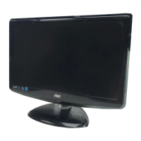
18.5" LCD Color Monitor AOC e940Swa
1
Service
Service
Service
Horizontal Frequency
30-80 kHz
TABLE OF CONTENTS
Description Page Description Page
Description
Page
SAFETY NOTICE
ANY PERSON ATTEMPTING TO SERVICE THIS CHASSIS MUST FAMILIARIZE HIMSELF WITH THE CHASSIS
AND BE AWARE OF THE NECESSARY SAFETY PRECAUTIONS TO BE USED WHEN SERVICING
ELECTRONIC EQUIPMENT CONTAINING HIGH VOLTAGES.
CAUTION: USE A SEPARATE ISOLATION TRANSFOMER FOR THIS UNIT WHEN SERVICING
Table Of Contents.......…….................……...........…........1
Revision List.........................………................……......2
1. Monitor Specification.................................………........3
2.LCD Monitor Description…………………………….......4
3. Operation Instruction…………...................…...........5
3.1 General Instructions.....................................…...........5
3.2 Control Button……………………………..……...........5
3.3 Adjusting the Picture...........................…............5
4. Input/Output Specification............……………............8
4.1 Input Signal Connector............…..……................8
4.2 Factory Preset Display Modes.........................9
5 Panel Specification.....…………………........................10
5.1 Display Characteristics………………………………10
5.2 Optical Characteristics………………………………..10
5.3 Parameter guide line for CCFL Inverter…………..10
6
Block
Diagram
1
1
Table Of Contents.......…….................……...........…........1
Revision List.…........................………................……......2
1. Monitor Specification.................................………........4
2. LCD Monitor Description…………………………….......6
3. Operation Instruction…………...................…...........6
3.1 General Instructions.....................................…...........7
3.2 Control Button……………………………..……...........7
3.3 Adjusting the Picture...........................…............7
4. Input/Output Specification............……………............11
4.1 Input Signal Connector............…..……................11
4.2 Factory Preset Display Modes...........................12
5 Panel Specification.....…………………........................13
5.1 Display Characteristics………………………………13
5.2 Optical Characteristics……………………………….14
5.3 Electrical Characteristics……………….…………..15
6. Block Diagram…….…................………….........17
6.1 Software Flow Chart…….…..........………….........17
6.2 Electrical Block Diagram………...………...…......19
7. Schematic……………………………………………. 22
7.1 Main Board…………..............................................22
7.2 Power Board....……………....................................26
8. PCB Layout..…………............................................31
8.1 Main Board……………......................................30
8.2 Power Board….....................................................32
8.3 Key Board……………….....................................36
9. Maintainability………...............................................37
9.1. Equipments and Tools Requirement.....................37
9.2. Trouble Shooting…………....................................38
10.Firmware and DDC Instruction………………….….44
11. White-Balance, Luminance adjustment.................45
12. Monitor Exploded View……..……………............47
13. BOM List....……....................................................48

Questions and Answers:

AOC e940Swa Specifications

General IconGeneral
BrandAOC
Modele940Swa
CategoryMonitor
LanguageEnglish

Summary

Service Manual

Safety Notice

Critical safety precautions for handling high voltage electronic equipment.

Important Safety and Handling Precautions

Revision List

1. Monitor Specification

Panel Specifications

Physical and visual characteristics of the monitor panel.

Resolution and Signal Specifications

Details on display resolution, scan ranges, and input signal types.

Physical and Environmental Characteristics

Dimensions, weight, operating temperature, and humidity requirements.

2. LCD Monitor Description

Monitor Block Diagram

Visual representation of the monitor's internal component connections.

3. Operating Instructions

General Operation and Control Buttons

Instructions for powering on/off and using the monitor's control buttons.

Picture Adjustment (OSD Setting)

Procedures for adjusting picture settings using the On-Screen Display (OSD).

Luminance and Image Setup Adjustments

Adjustments for brightness, contrast, color modes, and picture positioning.

Color Temperature and Boost Settings

Options for setting color temperature and enhancing picture features.

Picture Boost and OSD Setup

Adjusting picture frame properties and On-Screen Display configuration.

Extra Settings and LED Indicator

Additional monitor features and status indication via LED.

4. Input/Output Specification

D-SUB Connector Pinout

Pin configuration and function for the D-SUB signal connector.

Factory Preset Display Modes

List of supported display resolutions and their corresponding frequencies.

5 Panel Specification

Display Characteristics

Key display properties like size, resolution, brightness, and contrast ratio.

Optical Characteristics

Performance metrics related to viewing angle, response time, and color accuracy.

Electrical Characteristics of TFT LCD Module

Electrical parameters for the TFT LCD module, including voltage and current.

LVDS Signal Waveform and Backlight Unit Specifications

Details on LVDS signal characteristics and LED backlight unit performance.

6. Block Diagram

Software Flow Chart

Diagram illustrating the monitor's software operational logic.

6.2 Electrical Block Diagram - Scalar Board

Block diagram detailing the scalar board's components and interfaces.

6.2.2 Inverter / Power Board Block Diagram

Block diagram of the power supply and inverter board circuitry.

7. Schematic

7.1 Main Board Schematic

Circuit diagram showing the components and connections of the main board.

7.2 Power Board Schematic

Circuit diagram illustrating the power board's components and layout.

8. PCB Layout

8.1 Main Board PCB Layout

Top and bottom layer views of the main board PCB.

8.2 Power Board PCB Layout

Top and bottom layer views of the power board PCB.

8.3 Key Board PCB Layout

Visual layout of the key board's printed circuit board.

9. Maintainability

Equipments and Tools Requirement

List of necessary tools and equipment for servicing the monitor.

9.2 Trouble Shooting

9.2.1 Main Board Troubleshooting

Troubleshooting steps for problems related to the main board.

No Picture Troubleshooting

Steps to diagnose and resolve issues where the screen displays no image.

White Screen Troubleshooting

Diagnostic flow for issues causing a blank white screen display.

9.2.2 Power Board Troubleshooting

Troubleshooting procedures specific to the power board.

2. No Backlight Troubleshooting

Steps to diagnose and fix problems related to the backlight not functioning.

9.2.3 Key Board Troubleshooting

Troubleshooting steps for issues with the monitor's keypad or buttons.

10.Firmware and DDC Instruction

11. White-Balance, Luminance Adjustment

Chroma-7120 Setup and Color Temperature Selection

Sets up the Chroma-7120 and selects desired color temperatures.

Entering Factory Mode and Bias Adjustment

Procedure to enter factory mode and adjust bias settings.

Warm (6500K) Gain Adjustment

Calibrates gain for 6500K color temperature.

Normal (7300K) Gain Adjustment

Calibrates gain for 7300K color temperature.

Cool (9300K) Gain Adjustment

Calibrates gain for 9300K color temperature.

sRGB Color Temperature Gain Adjustment

Calibrates gain for sRGB color temperature settings.

Exiting Factory Mode

Steps to power off and exit the factory mode.

12. Monitor Exploded View

13. BOM List

Related product manuals