Power-up B
NTA47230-300A6 65 / 101
B.1.5 The USB connector
The TC-TM66XX range is fitted with a USB connector (mini B) intended for uploading new software versions and device
adjustment.
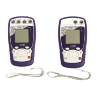
B.1.6 The screen
The TC-TM66XX range is fitted with a graphic LCD display with back-lighting. The display resolution is 160 x 160 pixels.
In normal operating conditions, the display is divided up into seven horizontal fields:
The 1
st
field indicates the operating mode (Measurement or emission).
The 2
nd
field indicates the date, time and battery charge.
The 3
rd
field is reserved for icons indicating the operating mode (related functions: Scaling, filtering…).
The 4
th
field indicates the operating mode, the gauge and certain related functions.
The 5
th
field indicates the value of the measurement or of the emission. These values are expressed in mV, Ohm,
°C, °F or as a %.
The 6
th
field indicates (in measurement mode) the min., average and max. values of the measurement.
Lastly, the 7
th
field indicates the functionality of keys F1 and F2.
The table below provides a definition of each pictogram displayed on the screen:
 Loading...