10
or
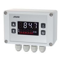
[UP] and [DOWN] (simultaneously) or [F]:
1. returning to the previous menu (one level higher),
2. cancelling changes of the edited value (flashing stops),
3. returning to the measurement display mode (holding time > 0.5s, except for [F])
c) additional functions of keys during the change (edition) of setpoints and other configuration parameters
Keys Description
[SET]+[UP] or
[SET]+[DOWN]
changing the value of the edited parameter (with a step of changes x10, keyes pressed
simultaneously)
[SET]+
[UP]+[DOWN]
restoring the factory value of the edited parameter (according to Table 8, chapter 8)
In addition, the speed of changing the edited value depends on the time the keys are held (the longer the faster).
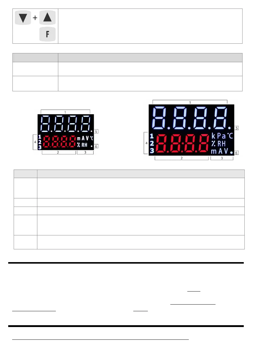
d) functions of the LED display elements
AR602.B AR632.B
AR642.B AR652.B
AR662.B AR682.B
Fig.7. View of all segments of the display
7.1. FUNCTION KEYS AND BINARY INPUT
Independent function keys [F] (not available in the AR602.B) and [SET] as well as the BIN binary input are used to
quickly run the programmed functions (with parameters 64: Fun F, 66: FunS and 65: Funb , described in chapter 8).
The BIN digital input cooperates with a bistable signal, i.e. the supplied signal (voltage or switch) must be
permanent (on/off type, active level: short-circuit or < 0.8V). Moreover, BIN has priority higher than the [F] and
[SET] keys. Activating or stopping the function is signaled by appropriate messages on the lower display
(described in
Table 8 and chapter 10). The action for [F] and [SET] is performed only in the mode with
measurement display (after holding time> 1.5 sec), for BIN - always (in every operating state).
8. SETTING CONFIGURATION PARAMETERS
All controller configuration parameters are contained in non-volatile (permanent) internal memory.
When switching on the appliance for the first time, the display may show an error signal related to the lack of
Element Description [and the method of marking in the content of the manual]
1, 2
upper and lower line for presenting (in 7-segment code) PV measured values and SP setpoints or
bargraph values (8-segment, chapter 8, parameter 73: dibo ) and other messages and errors (chapter
10)
3
units for displayed values (for measurements set with parameter 72: Wnit , description in chapter 8)
4 [1] [2] [3] - P1/SSR1, P2/SSR2, P3/SSR3 outputs activation signaling (LED alarm for AR602.B)
5
[T]: 1. analysis of the object for PID tuning signaling (auto-tuning) in the Auto mode (smart logic,
chapter 9.4),
2. time measurement signaling in the software algorithm (process controller with timer, chapter 9.6)
6
[Tx/Rx] - icon of the presence of USB, RS485 or Ethernet transmission and saving parameters in the
controller's memory