12
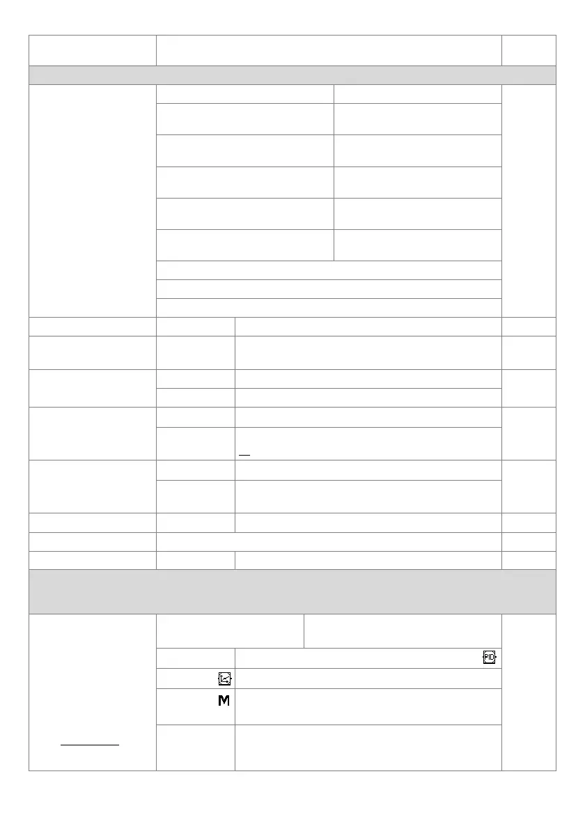
Table 8. List of configuration parameters
Parameter (index: name)
Value and range of variability of the parameter (value: name) and
description
Default
I. MEASURING INPUT CONFIGURATION, inCo submenu
0: inP
type of measurement input
0: Pt Pt100 sensor (RTD, -200÷850°C) 1: ni Ni100 sensor (RTD, -50÷170°C)
Pt
2: Pt5 Pt500 sensor
(RTD, -200÷620°C)
3: Pt10 Pt1000 sensor
(RTD, -200÷520°C)
4: tc-J thermocouple type J
(-40 ÷ 800 ° C)
5: tc-K thermocouple type K
(-40÷1200°C)
6: tc-S thermocouple type S
(-40 ÷ 1600 ° C)
7: tc-b thermocouple type B
(300÷1800°C)
8: tc-r thermocouple type R
(-40÷1600°C)
9: tc-t thermocouple type T
(-25÷350°C)
10: tc-E thermocouple type E
(-25÷820°C)
11: tc-n thermocouple type N
(-35÷1300°C)
12/13: 4/ 0-20 4÷20 mA / 0÷20 mA current signals
14/15: 0-10/ 60 0÷10 V / 0÷60 mV voltage signals
16: rES resistance signal 0÷2500 Ω
1: LirE line resistance (1) 0.00 ÷ 50.00 Ω
total line resistance for 2-wire RTDs and 2500 Ω sensors
0.00 Ω
2: cJtE temperature of
thermocouple cold ends
0: Auto
0.1 ÷ 60.0 ° C
automatic or constant temperature compensation of the
reference junction of thermocouples, Auto = 0.0 °°C
Auto
3: dot dot
position/resolution
0 / 1 no dot / 0.0 (2)or resolution 1/0.1°C for temperature
1
(0.1°C)
2 / 3 0.00 / 0.000 (2)
4: irLo lower limit for SP or
the bottom of the
indication range
/99.9 ÷ 1800 lower setting limit for setpoints SP (11: Set1 ÷ Set3 )
/99.9 °C
/999 ÷ 9999 (2)
beginning of the scale for the 0/4mA, 0V, 0Ω input and the
PV bargraph
5: irHi upper limit for SP
or the top of the indication
range
/99.9 ÷ 1800 upper setting limit for setpoints SP (11: Set1 ÷ Set3 )
850.0 °C
/999 ÷ 9999 (2)
end of scale for 20mA, 10V, 60mV, 2.5kΩ inputs and PV
bargraph
6: FiLt filtration (3) 1 ÷ 20
digital filtering degree (response time)
3 (~0.5s)
7: cALo zero calibration zero offset for measurements: -100.0 ÷ 100.0 °C or -1000 ÷ 1000 units (2) 0.0 °C
8: cALG gain 85.0 ÷ 115.0%
slope calibration (sensitivity) for measurements
100.0 %
II. CONFIGURATION OF OUTPUTS 1÷3 (P/SSR), submenu out1 ÷ out3, in 3 groups out1/2/3 there are the same sets of
parameters with different indices and numbering in the names (and possibly the range of variability), description
chapter 9
9: ctY1 control algorithm
16: ctY2 for output 2
(out2)
23: ctY3 for output 3
(out3)
Note (for 8/9 values):
if [F]/[SET] or BIN with the
0: oFF output permanently
switched off
1: onof ON / OFF with hysteresis
onof
2/3/4: Pid1/2/3
PID with parameter set 1/2/3 (chapter 9.3)
5/6: Prgc/A
software - main/auxiliary output (chapter 9.6)
7: hAnd
(manual)
manual (with the setpoint set with parameter 67: HSEt and
pulse period of the P/SSR output, 14: PEr1/2/ 3 )
8/9: StbF/n
safety thermostat STB (alarm with memory, LATCH),
emergency state open/closed (reset [F], [SET], BIN, chap .
7.1)