4
!
- direct or reversed copy of the output 1 state (applies to outputs 2 and 3, it can be used, for example, to
implement a DPDT change-over relay or to take over the function of a damaged P1)
- limitation of the maximum level of the output signal (power), also includes the connected mA/V analog
output
analogue output 0/4÷20mA or 0/2÷10V for adjustment or retransmission of measurements and setpoints:
- download of the control parameters from any connected output/alarm (1, 2, 3), both in automatic and
manual mode
- shock-free (soft) switching of the output signal, e.g. after changing the manual/automatic mode or control
start/stop
- correction (calibration) of the range of changes of the output signal (shift for the extreme values allowing to
obtain non-standard ranges, e.g. 2÷16mA or 1÷9V)
wide range of supply voltages (18÷265 Vac / 22÷350 Vdc) and built-in power supply for object transducers
24Vdc/30mA
clear LED display with adjustable brightness and signaling of the operating status (messages, errors, etc.):
- white color - measured value PV (upper line), typical measurement units (°C, %, %RH, mA, A, mV, V, m and
kPa, Pa, k for AR632.B/652.B/682.B or missing), symbols of outputs status and serial transmissions (1, 2, 3, . )
- red, bottom line - selectable SP setpoints or 8-segment bargraph for MV (control signal in the range of
0÷100%), PV (measurement), mA/V output signal or missing
optional RS485 serial interface, MODBUS-RTU protocol for reading measurements and parameters
configuration
optional Ethernet interface, MODBUS-TCP and MQTT protocols (for the Internet of Things IoT/M2M, cloud
and mobile applications), the possibility to exchange measurement and configuration data via the Internet
USB interface (micro USB connector, standard equipment, for parameter programming, measurement
preview and firmware update)
automatic/constant compensation of RTD and R line resistance and temperature of thermocouple cold
junctions
programmable input type, range of indications (for analogue inputs), options of control, alarms, display,
communication, access, and other configuration parameters
access to configuration parameters protected by a user's password or without protection
ways to configure parameters:
- from the membrane keyboard placed on the front panel of the device
- via the USB port, RS485 or Ethernet and the ARSOFT-CFG program (for Windows 7/10) or the user's
application (using the MODBUS-RTU and TCP communication protocols)
free ARSOFT-CFG software enabling the preview of the measured value and quick configuration of single or
ready sets of parameters previously saved on the computer for re-use, e.g. in other controllers of the same
type (duplication of configuration)
panel housing, protection class IP65 from the front (after using an additional accessory gasket or other seal),
IP54 without a gasket, AR662.B - housing for mounting on the TS35 rail (DIN EN 60715), IP40 (IP20 from the
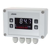
connectors side), AR632.B - industrial housing IP65 adapted to work in difficult environmental conditions, wall
mounting
modern technical solutions, intuitive and simple handling, high accuracy and long-term stability as well as
resistance to interferences
optional (in the ordering method): control outputs for SSR, analog output 0/2÷10V (instead of 0/4÷20mA) and
RS485 interface (for AR602.B excludes mA/V output and BIN input) and Ethernet (RJ45 connector)
available accessories (you can also buy it through the online store apar.sklep.pl):
- seal for IP65 tightness from the front (applies to panel housings)
USB cable (A - micro B) for connection to a computer, length 1.5 m
- USB to RS485 converter (with galvanic separation)
kit contents:
- controller (with mounting brackets for panel enclosures) as well as the user manual and warranty card
NOTE:
- before starting work with the controller , read this manual and correctly perform
mechanical and electrical installation and configuration of parameters in accordance with chapters 5, 6 and 8
(nomenclature of the parameters was adopted according to the principle: index from Table 8: name in the 7-
segment code, e.g. 0: inP),