9
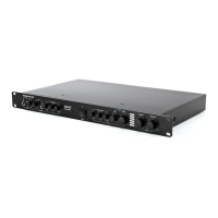
5. Channel 2 balanced input on 3 pole euroblock connector:
connect the line level input signal for channel 2 here. Line level
is 0 dBV.
6. Channel 2 input attenuator setting: Adjust the input attenuator
to the output level of your source. Make sure to avoid the clip
led lighting up at the strongest input peak level.
7. Channel 1 balanced input on 3 pole euroblock connector:
connect the line level input signal for channel 1 here. Line level
is 0 dBV. This connector is also used in the bridge mode.
8. Channel 1 input attenuator setting: Adjust the input attenuator
to the output level of your source. Make sure to avoid the clip
led lighting up at the strongest input peak level.
9. Bridge button: set to channel for normal operation. Set to
bridge mode for bridge mode operation.
10. HPF on/off dipswitch for channels 1 and 2: Set to on position to
enable the 250 Hz high pass filter.
11. Channel 2 and 1 output on euroblock: minimal load impedance
is 4 Ohms in stereo mode and 8 Ohms in bridge mode.
12. Fan area: keep free from dust and obstructions.
13. Mains voltage selector: set to 230 or 115VAC according to your
local mains voltage.
14. Mains inlet connecter: connect the mains cable supplied with
the unit here.