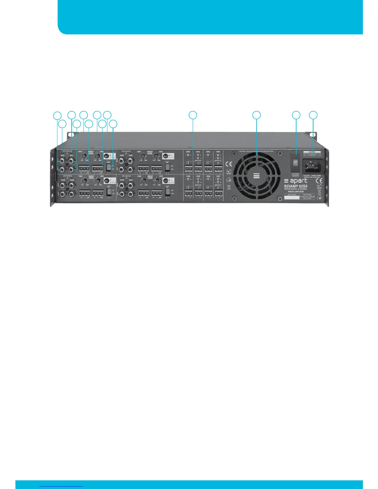
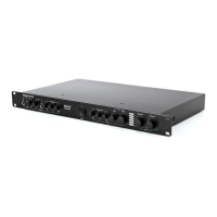
1. Channel 2 unbalanced input and link RCA connector: connect
the line level input signal for channel 2 here. Line level is 0 dBV.
Input and link RCA connector are internally connected 1 to 1.
2. Channel 2 overload led: when this led lights up, you are
overloading the input. Lower the input signal immediately to
prevent the amplifier from shutting down.
3. Channel 1 unbalanced input and link RCA connector: connect
the line level input signal for channel 1 here. Line level is 0 dBV.
Input and link RCA connector are internally connected 1 to 1.
This connector is also used in the bridge mode.
4. Channel 1 overload led: when this led lights up, you are
overloading the input. Lower the input signal immediately to
prevent the amplifier from shutting down.
1
4
6
2 5
Connections
3
8
7
9
10
11 12 13 14
Only channel 1 and 2 are explained. Channels 3 to 8 are
functionally identical to 1 and 2.