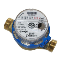
instrument,
flow direction, as an arrow,
V marking for water meters for vertical pipes,
H marking for water meters for horizontal pipes,
H • V for water meters for both vertical and horizontal pipes,
jet flow value Q
3
w m
3
/h,
marking of measurement unit in m
3
(on the counter dial),
value of the maximum pressure loss Ap,
value of the upper pressure limit: PN 16,
6. Conditions of correct installation of water meters
6.1 Place of installation for water meters should be easily accessible for installation, deinstallation and
operation, reading indications, separated from utility and industrial rooms. Protected from negative
atmospheric conditions and protected from the influence of electrical and gas installations. In case
there is no such place, the water meter may be installed in the water meter well, and additionally the
water meter and its equipment should be installed far enough from the well bottom. The well should be
fitted with a settling pond or a water outlet.
6.2. In the location of installation, the water meter cannot be at risk of being hit or be subjected to
vibrations caused by other devices in the vicinity, or subjected to high ambient air temperature,
contamination, flooding and corrosive action of the surroundings. Temperature in the installation
location should not be lower than 4°C. The water meter should be protected from influence of such
hydraulic phenomena such as cavitation or hydrodynamic water hammering.
6.3. Before, and after the water meter, provide the valves in order to cut off the water supply if there is
need for deinstallation or repair. Use valves which can entirely reveal the cross-section of a water pipe.
6.4. In case of expected water contamination during the time of operation install a filter or a settling
tank between a valve and a straight pipe section and before the water meter.
6.5. For an installation of a water meter which does not cause strain in the body it is recommended to
use compensative connectors installed at the output, which enable for the length reduction by
extending the telescopic connector sleeve.
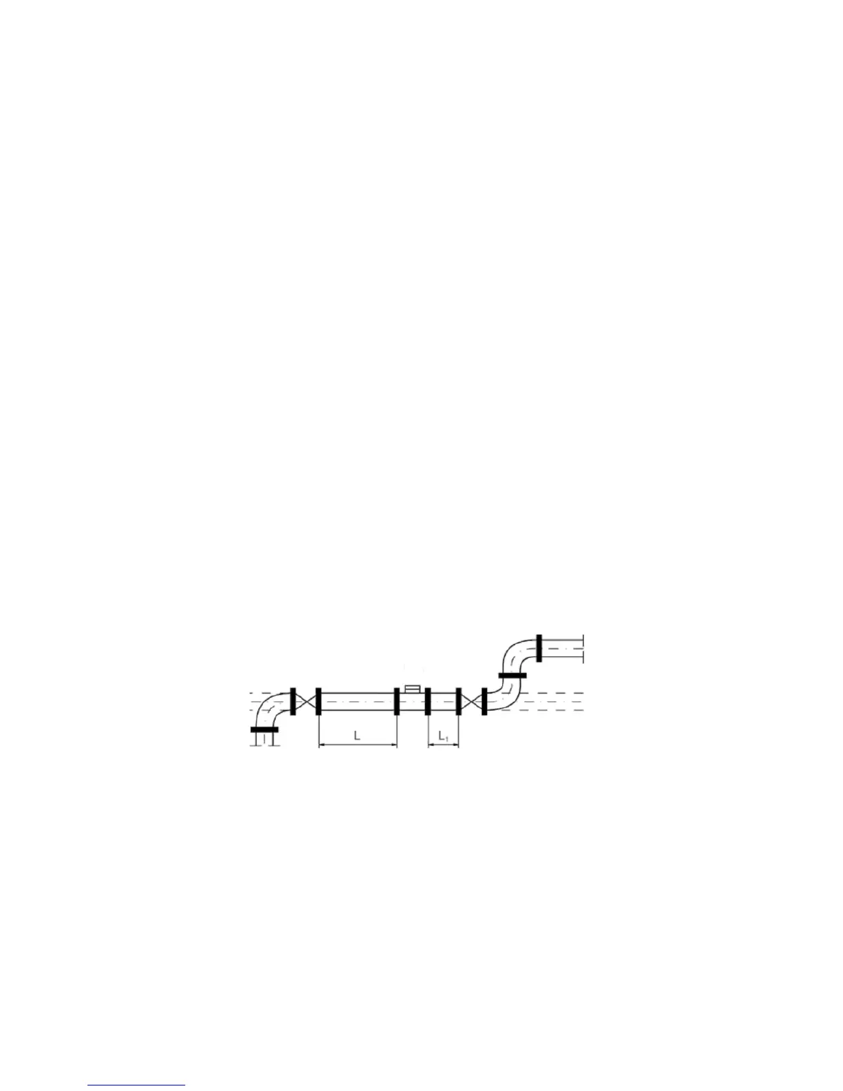
6.6. The pipe in the installation location should be shaped so that there is no possibility for an air
pocket to be created in the water meter. Water meter has to be entirely filled with water, so the water
pipe after the water meter cannot decline (Fig. 2).
Fig. 4 Water meter installation
6.7. Water meter should not be under risk of excessive strain caused by pipelines and equipment. If
necessary, install it on a pedestal or in a grip. What is more, the pipes connecting on the inlet and
outlet side should be adequately fastened, so that no part of the system is dislocated by the water
when the water meter is deinstalled or disconnected from one side.
6.8. During installing a meter in the water network, observe the correct water meter orientation
according to the design: for horizontal, vertical and diagonal operation (Table 2).
6.9. When using typical connectors, using other straight sections before (U0) and after (D0) the device
is not required.
However, in case of installing devices after a double elbow, non-return valve or a pump, provide a
straight pipe section L=5xDN (device nominal diameter) before the device (U5), and after the device
L1=3xDN (D3) (Fig. 2).
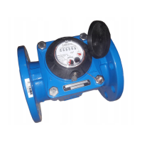
water meter