Installation and Configuration
4 Branch Current Monitoring Kit
How to connect the board to the monitoring unit.
1. Plug one end of the monitoring cable into the port on the board.
2. Plug the other end of the cable into a port on the PDU monitoring unit.
Note
If the board is on the left side of the PDU, the port will be on the bottom of the
board. If the board is on the right side of the PDU, the port will be on the top.
Note
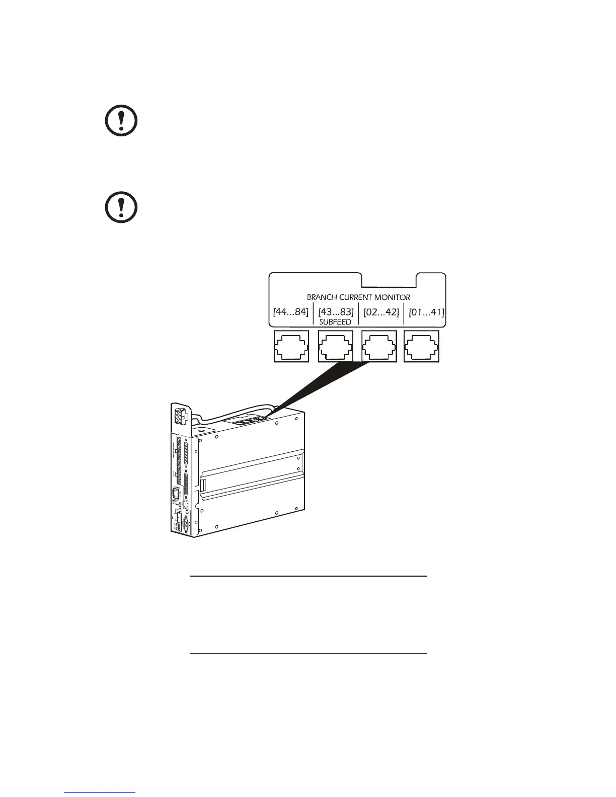
There are four available ports on the PDU monitoring unit to accommodate up to
four boards. The ports are labeled according to their circuit breaker assignments.
The following illustration shows the location of the ports on the PDU monitoring
unit and the label describing the circuit breakers assigned to each port.
Location of Board Circuit Breaker Numbers
Upper-left side of PDU 01...41
Upper-right side of PDU 02...42
Lower-left side of PDU 43...83
Lower-right side of PDU 44...84