10
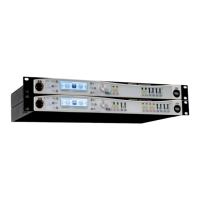
Front panel
Front and rear panel description
Front panel
General Controls:
The multi-function 240 x 64 pixel LCD graphic display
allows control of the Intelli-X2’s audio and control functions
via the unit’s menu system.
The h button is used in conjunction with the menu system.
The I button is used in conjunction with the menu system.
The BACK/HOME button is used in conjunction with the
menu system.
The ENABLE button is used in conjunction with the menu
system.
The UNDO button is used in conjunction with the menu
system.
The Function (Fn) button is used in conjunction with the
menu system.
Note – keys 2 to 7 also have “soft” functions which vary
with the menu pages.
Rotary control for menu navigation, data entry, etc. The
control can also be pressed inwards, to perform an “Enter”
action in the menu system.
The MUTE/SELECT button denes the function of all
channel “soft” buttons [13] and [16]. It incorporates a
bicolour LED, which illuminates red = ”Mute”, green =
”Select”. Note that the soft buttons remain in “Mute” mode
until the appropriate menu level has been entered.
A full description of the menu system is given in Section
“The Menu System”.
The front panel Ethernet port allows convenient connection
of a PC for remote control purposes. There are two further
Ethernet ports on the rear panel for permanent network
connections in a xed installation.
The white REMOTE LED is concerned with control via
Inteli-Ware software. It illuminates steadily when the unit is
connected to a network and a valid IP address has been set
up, and will blink when unit parameters are being changed
via Intelli-Ware.
The Intelli-X
2
is powered on and off by a front panel switch;
an adjacent white LED illuminates when the unit is powered.
Input Controls:
Each input channel has a “soft” button below its meter,
which performs either a Channel Select function (in
conjunction with the menu system), or mutes the input
channel, depending on the setting of the Master MUTE/
SELECT button [9].
Each input channel has a 6-segment tricolour LED bargraph
meter which indicates the signal level in the channel. The
meter is calibrated in dBFS, where 0 dB corresponds to
digital clipping. The bottom ‘Sig’ segment illuminates at an
input level of -48 dBFS. The top ‘Comp’ segment illuminates
when gain reduction in the channel is being applied by the
compressor.
Input channel AES LED(s). Each pair of input channels has
a red LED which illuminates if those channels are selected
to be an AES-3 digital input pair. Two LEDs are tted to the
Intelli-X
2
48, and one to the Intelli-X
2
26.
Output Controls:
Each output channel has a “soft” button, whose function is
identical to the input channel buttons [13].
7-segment bargraph metering is provided for each output
channel; the meters are similar to the input channel meters
[14], but the highest segment indicates operation of the
output channel limiter, and the bottom ‘Sig’ LED illuminates
when the output channel signal level is 48 dB below the
RMS limiter threshold.
Output channel AES LED(s). These perform the same
function as [15] for the output channels. Four LEDs are
tted to the Intelli-X
2
48, and three to the Intelli-X
2
26.
3
4
2
1
5
6
7
8
9
10
11
12
13
14
15
16
17
18
11 6 5 1 2 8 14 17 12
10 7
3 4
9
13 15 18
16
 Loading...