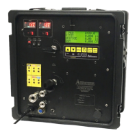
Assembly
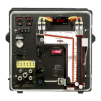
1. Remove the door panels from the front and rear of the VersaCase frame. Place the VersaCase
on a flat surface so that the hinges are to the left of the VersaCase.
2. If the stainless steel panel is not installed, install it using the 8/32 by 1/4-in screws. On the
VersaCase support frame, locate the line of screw holes that run from top to bottom on each side
of the case. Counting up from the bottom of the VersaCase frame, secure the panel using hole
positions six (6), ten(10), fifteen(15) and nineteen (19). When installing the panel, make sure that
the mounting surface of the panel faces toward the rear of the case. (see Figure 3)
3. Mount the nine VC2-50 clamps to the predrilled panel, using two 3” screws and the large brass
knurled thumbnuts for each clamp. Fill the burette water jacket with distilled water to the top, and
cap using the #15 screw cap. (The addition of a few drops of chlorine bleach will help to hinder
mold growth.) Install the burette being certain that the numbered markings face the operator.
Secure the burette in the clamp using two of the large knurled brass thumb nuts. (Figure 3)
4. The carbon dioxide (CO
2
) absorption pipette assembly is installed to the immediate right of the
burrette using another VC-50F clamp. Mount the clamp to the top slot of the crossbar. Assemble
one of the contact pipettes by placing one #30 bored cap and one #30 seal ring over the contact
pipette stem, and inserting the stem of the contact pipette into the pipette bottle Tighten the cap
to form a leak-free seal. Mount a second clamp to the middle crossbar on the top slot, directly
beneath the second clamp on the top crossbar. When installing the CO
2
pipette, make sure that
it is positioned so that the 3-way stopcock valve on the contact faces towards the operator.
(Figure 3)
5. The oxygen (O
2
) absorption pipette will be installed to the immediate right of the CO
2
pipette
assembly. Mount two VC-50F clamps, one on the bottom slot of the top crossbar and one to the
bottom slot of the middle crossbar. Place one #30 bored cap and one #30 seal ring on the
contact pipe stem. Insert the stem into the pipette bottle and tighten the cap to form a leak free
seal. Secure the O
2
assembly in the clamp using four of the large knurled brass thumb nuts,
making sure the stopcock valve is facing the operator. (Figure 3)
6. If carbon monoxide (CO) analyses are required, use the remaining contact pipette assembly for
this purpose. Place a #30 bored cap and #30 seal ring over the contact stem and insert the stem
into a pipette bottle. Tighten the cap to form a leak free seal. Mount two VC-50F clamps to the
extreme right of the case, both on the top slots of the top and middle crossbars. Secure the
pipette assembly in the clamps using four of the large knurled brass thumb nuts, making sure the
stopcock valve is facing the operator. (Figure 3)
7. Secure the aspirator bottle to the clamp at the bottom of the panel. Attach a 30” piece of rubber
tubing to the hose barb of the aspirator bottle and hose barb of the burette. (Figure 3)
8. Connect the burette and the absorption pipettes together using the 1 1/2 inch pieces of the
supplied rubber tubing. Check to ensure that the absorption pipettes are securely attached to the
support clamps and that the stopcock bodies are free of debris to form leak-free seals.
VSC-33
APEX INSTRUMENTS, INC.
9