1
SUPER
AVC-R
Super Actuator Valve Controller
Type
- R
1.
lulroductioll
Thank
you
for
purcliasing
the
A'PEXi
Super A
VC-R.
This
is
a
highly
efficient boost
controUer
excelling
in
rapid boost response and stability.
This
'unit
can
be installed
on
virtually
any
turbo vehicle ranging
from
nomlal
engines
to hard tuned
engines
with
its self-learning
function. Furthermore, the standard
real
time
boost pressure
display
and
real
time
injector pulse
display
have
been
included
in
this
unit.
Please
be
sure
to
read this
manual
completely
and
use
the
ullit
properly.
2.
!W
ARNlNGS - Please be sure
10
read-
• Although this
unit
may
be installed on virtually
any
turbo vehicle ranging
from
normal.
modified
engines.
to
turbo upgrades, the
unit
utilizes the injector
signal
for
its self learning function
which
limits
its usage
to
Electronically Controlled
Fuel
Injection System
Vehicles
Running
On
Gasoline.
Please be aware
that
the Self- Learning
mode
cannot have
an
accurate reading irthe injector pulse
display does not
work
and if the installation vehicle
has
an
electrical current controller for the
injector
signal.
(For instance: I'Z 3 1 ,
It
31
)
"
This
unit
may
be
programmed
up
to a
maximum
boost pressure of2.0 ( kglcm2.) Raising the
boost pressure above
normal
settings
which
exceeds the
vehicle's
fuel
supply
margin
lIIay
lead
to
engine
failure.
When
raising boost pressure, please raise the boost according to the margins
of
the
injector, air
flow
meter, and
fuel
pump
of
the engine
and
turbo .
• Please be warned that
our
t'ompally
is
1I0t
respollsible for ANY damages incurred
to
the
engine, turbo alld all I'elated
cOlllllOllents
due
to
IInnecessary alld excessive boost pres!llJre
levels. •
"
Some
vehicles
may
have
a
fuel
cut
system
when
the boost pressure
has
been raised. Please
release
the
fuel
cut
system
in
these
cases.
Please contact our
company
if there are
lIny
problems
releasing the
fuel
cut
system.
• Please
use
extra caution
when
proceeding
with
wiring or
pilling
procedures. olli· cOlllpany
is
1101
responsible for any vehicle trouble resulting from falllty blstallaHoll.
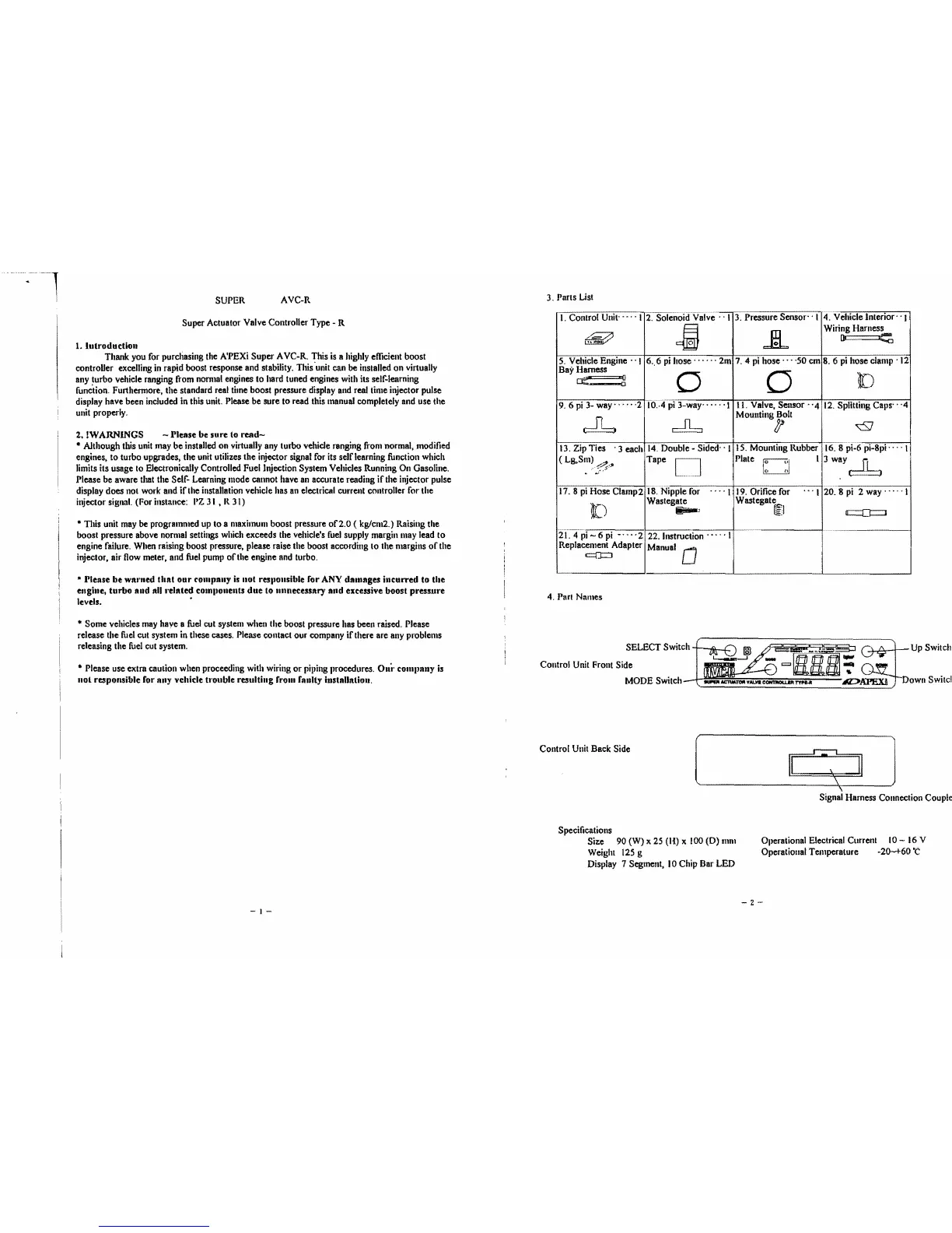
3.
Parts
List
I. Control
Unit·
....
I
4.
Vehicle Interior' . I
Wiring Harness
3.
Pressure Sensor-' 1
2.
SolenoiifValve . -I
~
[ll
~
..HL
8.6
pi
hose
clamp
'12
Bay
Harness
5.
Vehicle Engine' '1 6
..
6
pi
hose······
2m
7.4
pi
hose'"
·50
cm
[)
Cf!"----ii
0
0
9.
6
pi
3- way'
....
·2
10
...
fpi
3-way-
..
-.
'1
II.
Valve.
Sensor
-'4
12.
Splitting Caps'-
Moullting Bolt
,
<::SJ
16.
8pi-6 pi-Spi' -
_.
I
(
Lg,SIII)
/~.,
IS. Mounting Rubber
13. Zip Ties
. 3
each
14.
Double - Sided' . 1
Plate
Tape
13Wl.ly~
..
,
..
;:,:::.
...
\
20.
8
pi
2 way'
....
I
Wastegate
18.
Nipple
for
.... \
17.
8
pi
Hose Clamp2
19.
Orifice for
Wastegate
....
[)
~l
~l
o:::::::::!J=J
21.4pi-6pi
-····2
22.
Instruction
.....
\
Replacement Adapter
Manual
0
c:::(J:::l
4.
ParI
Names
SELECT Switch..c.:
II
.t:\
fi'Il
~.
.Jl
....
§5:J
!.:::I
/\
1
Up
Switch
Control
Unit
Front Side
~
1IC:IIo/t;l!olt::¥d
--~--
••.
-.
Down
Switci
-t
MODE
Switch
Control
Unit
Back
Side
[
GJ]
Signal
Harness Connection Couple
Specifications
Size
90
(W)
x
25
(H) x
100
(D)
mill
Ollerational Electrical Current
10
-
16
V
Weight
125
g
Operational Temperature -20-+60'C
Display
7 Segment,
10
Chip
Bar
LED
-2-
1-
 Loading...