--'1
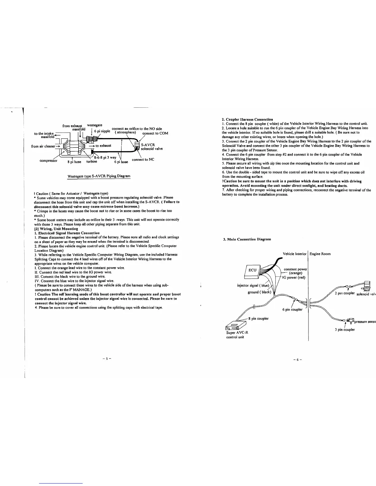
frolll exha'!st wastegale connect an orifice
to
the NO side
l1Ialll!fold
16
pi
nipple ( atmosphere) connect
to
COM
*1
\ /
~
1 \
~S-AVCR
solenoid valve
"\
'J'
-t' I " 8-6-8
pi
3 way
,'4
connect
to
NC
compressor
8 pi hose
turbine 6
pi
hose
Wastegate type
S-A VCR Piping Diagram
! Caution ( Same for Actuator I Wastegate type)
• Some vehicles may come equipped with a boost pressure regulating solenoid valve. l'Ie8se
disconnect the hose frolll this unit and cap the unit olTwhen installing the S-AVCR. ( Fallul'e to
disconllect this solenoid valve lIIay calise
extreme
boost incrense.)
• Crimps
in
the hoses
lIIay
cause the boost not to rise
or
in some cases the boost
to
rise too
much.)
..
Some
boost meters may include an orifice
in
their 3 -ways. This unit will not operate correctly
with those 3 ways. Please keep all other piping separate from this unit.
12)
Wiring,
Unit
Mounting
1. Elech·icnll Sigllal
lIamess
Connection
.
1.
Please disconnect the negative terminal
of
the battery. ('lease nole
all
radio and clock settings
011
a sheet
of
paper as Ihey may be erased when the terminal is disconnected.
2.
Please locate tlul vehicle engine control unit. (Please refer to the Vehicle Specific Compuler
Location Diagram)
3. While referring to the Vehicle Specific Computer Wiring Diagram, use the included Harness
Splitting Caps to connect the !1lead wires off
of
the Vehicle Interior Wiring Harness
to
the
appropriate wires on the vehicle computer.
I. Connect the orange lead wire
to
the constant power wire.
II. Connect the red lead wire to the IG power wire.
III. Connect the black wire
to
the ground wire.
IV. Connect the blue wire to the injector signal wire.
( Please
be
sure
to
connect these wires to the vehicle side
of
the harness when using sub-
computers such as the
F MANAGE.)
I
Cautioll
The
self
learning
lIIode
of
this boost
controller
will
not
ollernte alld prollel' boost
cOlltnl
call1lot be achieved ulliess
the
injector
sigllal
wire
is
cOllnected, J'lease
be
5111'e
to
connect
the
injector
signnl
wiJoe.
4.
Please be sure to cover
all
connections using the splitting caps with electrical tape,
-5-
2.
Coupler
llarness
COllnection
I.
Connect the 8 pin coupler
(white)
of
the Vehicle Interior Wiring Harness
to
the control unit.
2. Locate a hole suitable to run the 6 pin coupler
of
the Vehicle Engine Bay Wiring Harness into
the vehicle interior.
Ifno
suitable hole is found, please drill a suitable hole.
(Be
sure not to
damage
allY
other existing wires,
or
hoses when opening the hole.)
3. Connect the 2 pin coupler
of
the Vehicle Engine Bay Wiring Harness
to
the 2 pill coupler
of
the
Solenoid Valve and connect the other 3 pin coupler
of
the Vehicle Engine Bay Wiring Harness to
the 3 pin coupler
of
Pressure "Sensor.
4. Connect the 6 pin coupler from step #2 and connect it
to
the 6 pin coupler
of
the Vehicle
Interior Wiring Harness.
5. Please secure all wiring with zip ties once the mounting location for the control unit and
solenoid valve have been found.
6. Use the double - sided tape to mount the control unit and
be
sure
to
wipe
01T
any excess oil
from the mounting surface.
ICaution
be
sure
to monllt
the
nnit
in
II
position
which
does
IIOt
illterrere
with
driving
opel'atioll. Avoid
mounting
the
unit
nnder
direct·
sunlight,
alld
beating
ducts.
7.
After checking for proper wiring and piping connections, reconnect the negative terluina!
of
the
battery
to
complete the installation process.
3.
Main
COllnection
Diagram
Vehicle Interior
I Engine Room
,~
2 pili coupler solenoid
valv
f
~pressure
senso
3 pin coupler
~~PI~
Super AVC-R
control unit
-6
 Loading...