-1
3.
Letting go
ofthe
button at the specified boost level
will
return the screen to the monitor mode
completing the setting.
t.Qjl
/can
*~
••
..
tiil
/c
=rs"
*~
O·
_____
A>&l'EJl
A>.iIIim1
- - -
_.
. -
IR
6~
L2S;ov
____
lID
5-568~
.....
0
..
hX:
I.:.!'
kg/COl:.! for preset A Displays present
OOOS[
pressure
IMPORTANT·
Pressing the UP/DOWN switch in succession
aner
pressing
the
SELECT
switch allolVs those cOllllllands to remllin elTective.
Thus
pressing
the
button
only once will
return
the
unit
bacl, to nionitor mode.
3. P."eset Boost Dnty Setting
Although this unil uses feedback management and the selflearning function to
automatically control the boost pressure to the specified setting. the valve driving power duty
must stay within a certain limit. Since this limit varies
from
vehicle to vehicle depending on engine
tuning,
it
is
llecessary to set each and every individual vehicle.
3-1
Actuator
Type
I. Press the SELECT switch for longer than 3 seconds.
2.
Be sure to check that all
of
the LED'S other than the SUPER AVC-R logo and the digital bar
graph have been turned OFF
~11.fJ
M-~~
09
nmt
'o-j21~
o~
__
Ml'I'Ut«OR
...
oc.;n;;;;::;:;;,."..,.
Il>JUIEXI
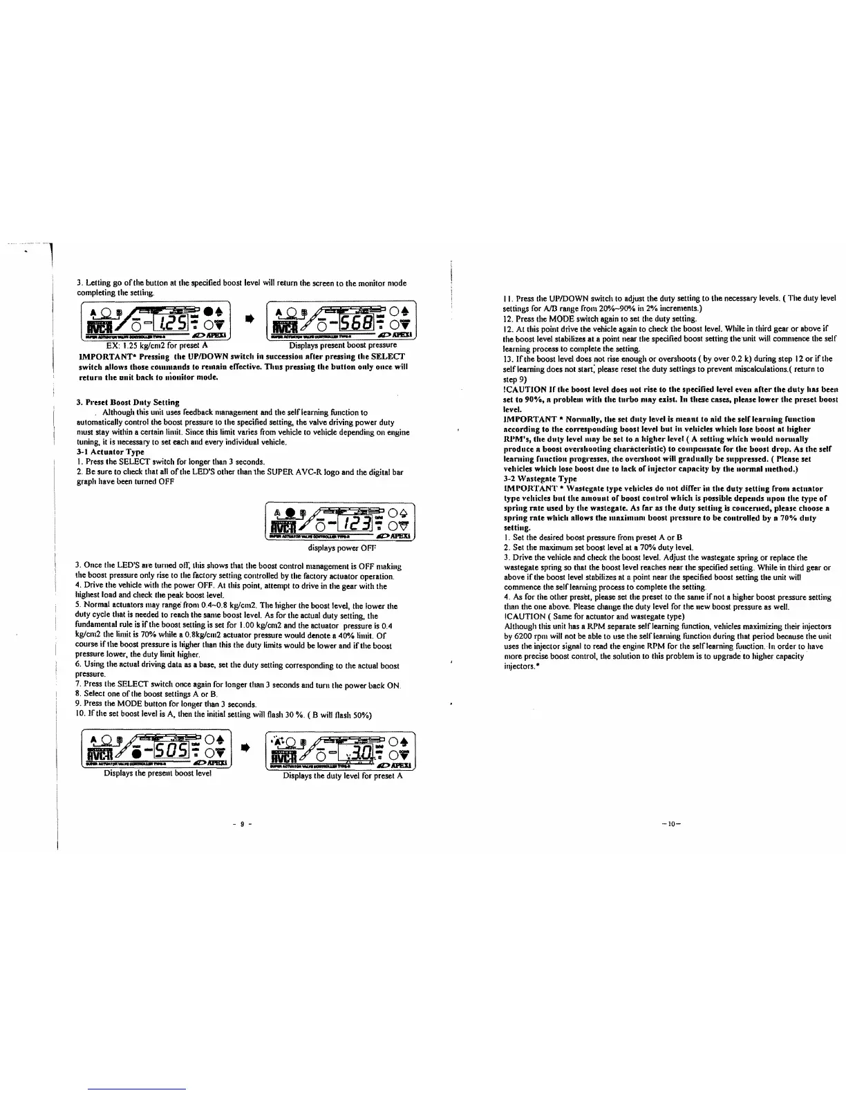
displays power OFF
3.
Once the LED'S are turned on:
Ihis
shows that the boost control management
is
OFF making
the boost pressure only rise to the factory setting controlled
by
the factory actuator operation.
4.
Drive the vehicle with the power OFF. At this point, attempt to drive in the gear with the
highest load and check the peak boost level.
5.
Normal actuators may range' from 0.4-0.8 kg/cm2. The higher the boost level, the lower the
duly cycle that
is
needed to reach the same boost level.
As
for the actual duty setting, the
fundamental rule
is
if
the boost setting
is
set for 1.00 kg/cm2 and the actuator pressure
is
0.4
kg/cm2 the limit
is
70% while a 0.8kg/cm2 actuator pressure would denote a
400/0
limit.
Of
course
if
the boost pressure is higher than this the duty limits would be lower and
if
the boost
pressure lower, the duty limit higher.
6. Using the actual driving data as a base, set the duty setting corresponding to the actual boost
pressure.
7.
Press the SELECT switch once again for longer than 3 seconds and turn the power back
ON.
8.
Select one
of
the boost settings A or
B.
9.
Press the MODE button for longer than 3 seconds.
10.
If
the set boost level
is
A,
then the initial selling
will
Hash
30 %. ( B willllash 50%)
_0+
-y'~iSo5j;g;
I
..
___
A>APEIl
HV
..... v V
d~7-:
o.
_.
-_.-
A>APEIl
Displays the present boost level
Displays the duty level for preset A
- 9 -
II.
Press the UPIDOWN switch to adjust the duty setting to lhe necessary levels. ( The duty level
settings for
AJD
range from
200/0-90"10
in
2% increments.)
12.
Press the MODE switch again
to
set the duty setting.
12.
At this point drive the vehicle again to check the boost level. While
in
third gear
or
above
if
the boost level stabilizes at a point Ilear the specified boost setting the'unit
will
commence the self
learning process
to complete the setting.
13.
If
the boost level does not rise enough
or
overshoots
(by
over 0.2 k) during step
12
or
ifthe
selflearning does not start: please reset the duty settings to prevent miscalculations.( return to
step 9)
!eA
UTlON
Ir
the
boost level does not rise to
the
specilied level even
aner
the
duty
has beeu
set to
90%,
a problelll with
the
turbo
may exist. In these cases, please lower the preset boost
level.
IMPORTANT
* Nonllally,
the
set dllty level
is
meant
to nid tile selrlenMling runction
according to the corresllondillg boost level
but
ill vehicles whieh lose boost
at
higher
IU'M's,
the
duty
levellllay be set to a
higher
level ( A setting which wOllld lIonllnlly
produce
a boost ovel'shooting charncteristic) to
compensate
ror the boost
dl'OII.
As
the
selr
leantillg rnllction
PI'Ogl'esSes,
the overshoot will gradually be SlII,pressed. ( Please set
vehicles which lose boost
due
to lack
or
injector
capacity by tile
uormalmethod.)
3-2 Wastegnte Type
IMl~ORTANT
• Wastegnte tYlle vehicles
do
1I0t
differ in
the
duty
setting rrom
actnator
type vehicles bllt the
amount
or
boost
COil
trol which
is
possible depellds npoll
the
tyl,e
or
sllring
mte
used by
the
wnstegate.
As
rar
as
the
duty
setting
is
conceMled, please choose a
spring
mte
which allows the
IIIl11illlllm
boost III'essure
to
be
controlled by a
70%
dllty
setting.
I. Set the desired boost pressure from preset A
or
B
2.
Set the maximum set boost level at a 70% duty level.
3.
Drive the vehicle and check the boost level. Adjust the wastegate spring
or
replace the
wastegate spring so that the boost level reaches near the specified setting. While
in
third gear or
above
if
the boost
level
stabilizes
at
a point near the specified boost setting the unit
will
commence the self learning process to complete the setting.
4.
As
for the other preset, please set the preset to the same Ifnot a higher boost pressure setting
thnn the one above. Please change the duty level for the new boost pressure as well.
!CAUTION ( Same
for
actuator and wastegate type)
Although this unit has a RPM separate selflearning function, vehicles maximizing their injectors
by
6200 rpm
will
not be able to lise the self learning lunction during that period because the unil
uses the injector signal to read the engine
RPM
for the selflearning function. In order to have
more precise boosl control, the solution to this problem is to upgrade to higher capacity·
ir~ectors.
•
-10-
 Loading...