-1
5.
Froduct
Main
Features
..
Boost response is extremely fast.
...
Excels
in
stabilizing boost levels. ( Especially
in
higher RPM's)
...
2 Mode boost preset function
...
Self -learning function maximizes use
of
a highly efficient CPU
...
Achieves a level
of
perfect management
of
RPM specific boost management
by
combining the
injector signal with the RPM signal.
* Applies the best suited boost control even under high RPM levels .
...
Utilizes a wide- range absolute pressure sensor which accommodates high boost settings and
changes in the air pressure.
...
Includes a high precision real time boost display and injector pulse display along with a digital
and bar graph display. (Includes a maximum injector pulse indicator)
...
For extra safety, a preset boost locking feature is included.
(set-up)
..
Easy
to
mount 1/4 DIN case size.
6. Inslnilation
Frocedures
!
Cautioll
..
Please be sure that the engine has fully cooled down before attempting any piping installation.
..
Please be sure to disconnect the negative terminal
of
the battery before attempting any wiring
installation .
...
Please mount this unit away from direct sunlight.
..
Please mount this unit where the driver cannot reach. ( Approximately
SO
cm away from the
drivers seal)
LIJ
Fundnmentnl
Filling
I,
Actuator
TYlle
1.
Discollnectthe hose from the turbine compressor to the actuator.
2. Cut the necessary length
of
6
pi
hose and connect the compressor side
to
the NO side
of
the
solenoid valve and the actuator side to the COM side
of
the valve as shown
in
the diagralll
..
(Leave the
NC
side
of
the valve open.)
3. Mount the solenoid valve away rrolll high telllllelllture
areas
with the included bolts and
Rubber
Mounting
Flate.
!
Cantion
Installing the solenoid valve
near
high
temperature
areas
or
monnting
the
valve
withont
the
I1Ibber mOllnting Idate lIIay shol'ten
the
life
span
or
the valve
and
in the
wont
cnses
break
the valve.
4. Locate the hose
frOI1l
the surge tank to the
fuel
pressure regulator
and
insert the 4
pi
3 way into
the 4 pi hose. Connect another 4
pi
hose
to
the open side, cut an appropriate length
and
connect it
to
the pressure sensor.
5.
Mount the pressure sensor nwny
fl"olll
high
tempernture
nreas and use the included bolts to
Illount the sensor with the connected hose facing downwards.
-3-
!
Cantion
Installing
the
III'esslIl"e
senSUI"
neal" high tellll,el"atUl"e al'eas lIIay affect
the
accuracy
or
the
sensol'
aud
in
the
WOl'St
cases bl"enl'
the
SenSOI",
6. Secure all hose connections with either a hose
clamp
or
n zip tie and make sure that none
of
the hoses
are
crimped .
NC to Atmosplu
~
?:nnecttoNO
fi.'\
S-AVCR
Solenoid Valve
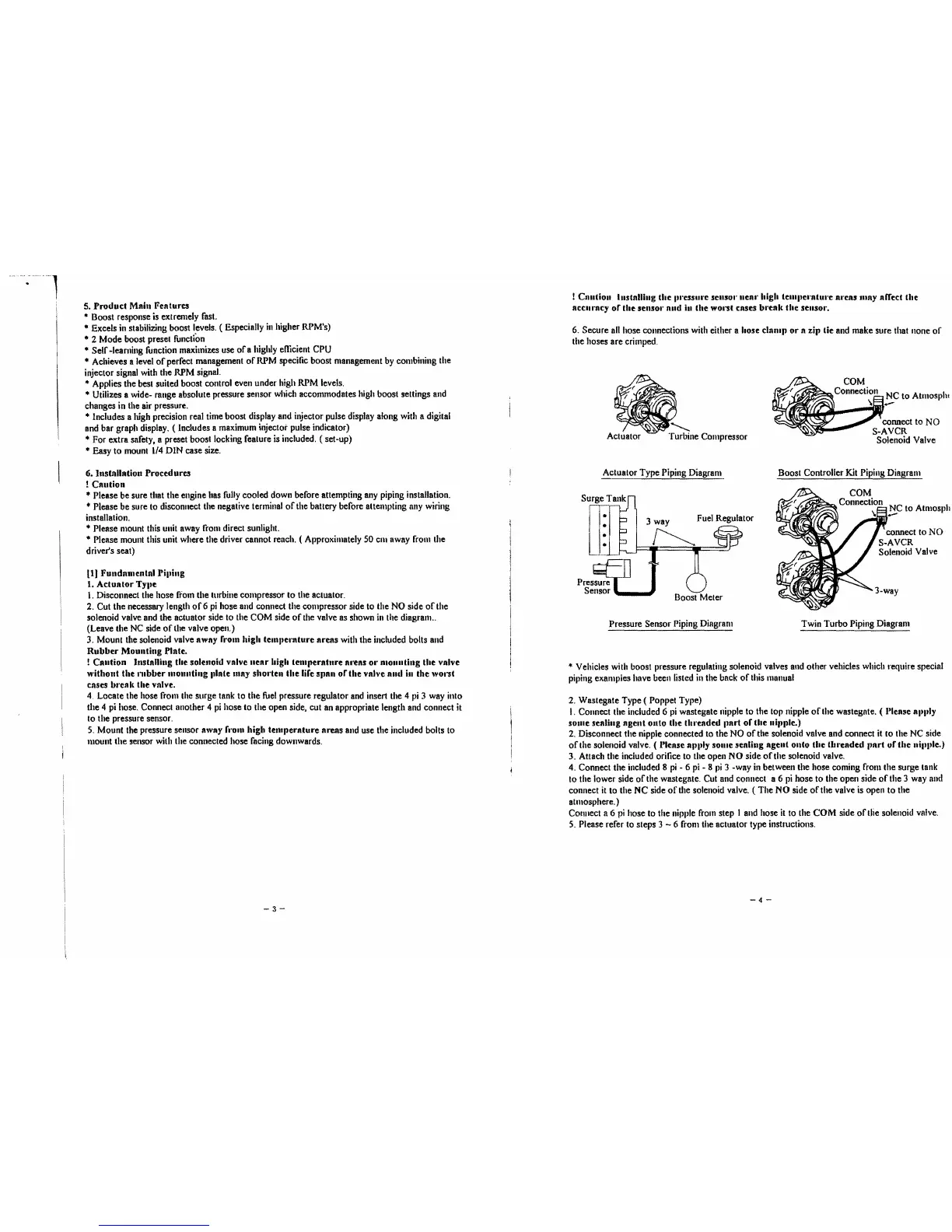
Actuator Type Piping Diagram Boost Controller Kit Piping Diagram
COM
Connection NC to Atl1losph
\13-
Pressure Sensor Piping Diagram Twin Turbo Piping Diagram
..
Vehicles with boost pressure regulating solenoid valves and other vehicles which require special
piping examples have been listed
in
the back
or
this manual
2. Wastegate Type ( Poppet Type)
I.
Connect the included 6
pi
wastegate nipple to the top nipple
of
the wastegate. ( l'lease allilly
sOllie sealing
agent
onto
the tlll"eaded Ilart
of
the
nipple.)
2,
Disconnect the nipple connected to the NO
of
the solenoid valve and connect it
to
the NC side
of
the solenoid valve. ( I'lease n"I"Y
SOllie
sealing agent
OlltO
the
thl"eaded
part
ur
the
lIi"I,le.)
3. Attach the included orifice
to
the open
NO
side
ofthe
solenoid valve.
4. Connect the included
8
pi
- 6 pi - 8
pi
3 -way
in
between the hose coming froll! the surge tank
to
the lower side
of
tile w8stegate. Cut and connect a 6
pi
hose
to
the open side
orthe
3 way and
connect
it
to
the
NC
side
of
the solenoid valve. ( The
NO
side
or
the valve is open to the
atmosphere. )
COllnect a 6
pi
hose to the nipple
froll!
step I and hose
it
to the
COM
side
orthe
solenoid valve.
S.
Please rerer to steps 3 - 6 from the actuator type instructions.
4-
 Loading...