ARCHMI-8XX Series User Manual
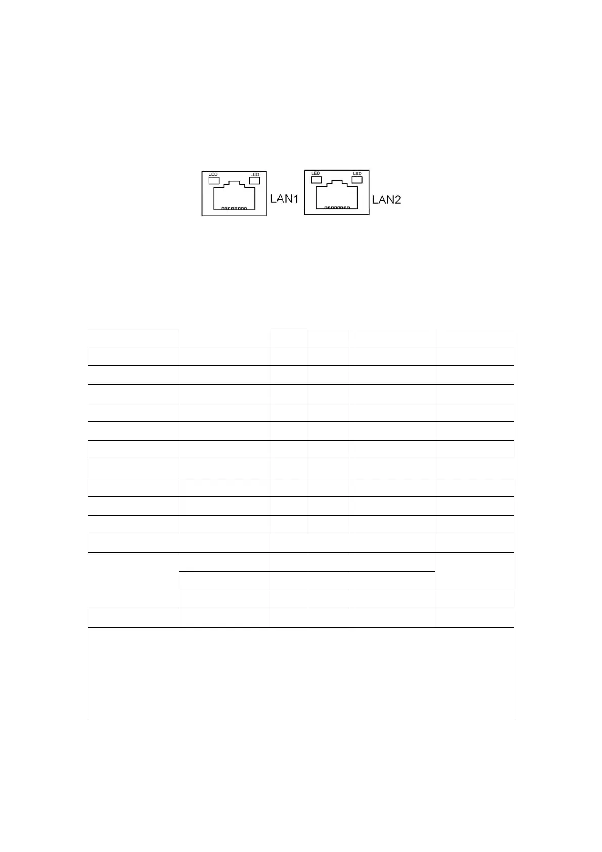
34. LAN1/LAN2:
LAN1/LAN2: (RJ45 Connector), Rear LAN port, Two standard 10/100/1000M
RJ-45 Ethernet ports are provided. Used intel 82574L chipset, LINK LED (green)
and ACTIVE LED (yellow) respectively located at the left-hand and right-hand
side of the Ethernet port indicate the activity and transmission state of LAN.
35. BUZ1:
Onboard buzzer.
36. CN2:
(DF13-30P Connector) For expand output connector, It provides eight GPIO,
one RS422 or RS485, one USB2.0, one Power on/off, one Reset.
COM5/COM6 BIOS Setup:
Advanced/IT8518Super IO Configuration/Serial Port 1 Configuration【RS-485】
Advanced/IT8518Super IO Configuration/Serial Port 1 Configuration【RS-422】
Advanced/IT8518Super IO Configuration/Serial Port 2 Configuration【RS-485】
Advanced/IT8518Super IO Configuration/Serial Port 2 Configuration【RS-422】
37. EC_GPIO1:
(2.0mm Pitch 1X10 Pin Header)For expand connector, it provides brightness adjustment
function
 Loading...