Home
Aplex
Touch Panel
ARCHMI-807
Page 45
Aplex ARCHMI-807 - Page 45
108 pages
Manual
Save Page as PDF
To Next Page
To Next Page
To Previous Page
To Previous Page
Loading...
ARCHMI-8XX Series U
ser M
anual
44
Pin#
Signal Name
1
Ground
2
GP
A0_ONOFF
3
GP
A1_SPK
-
4
GPE6_BKL
T
-
5
GPE0_BKL
T+
6
SPK
GPC3_SPK+
7
BKL_CTRL_PWR
8
ADC6_BKL
T_CTRL
9
ADC7_L_SENSE
10
3.3V
38
.
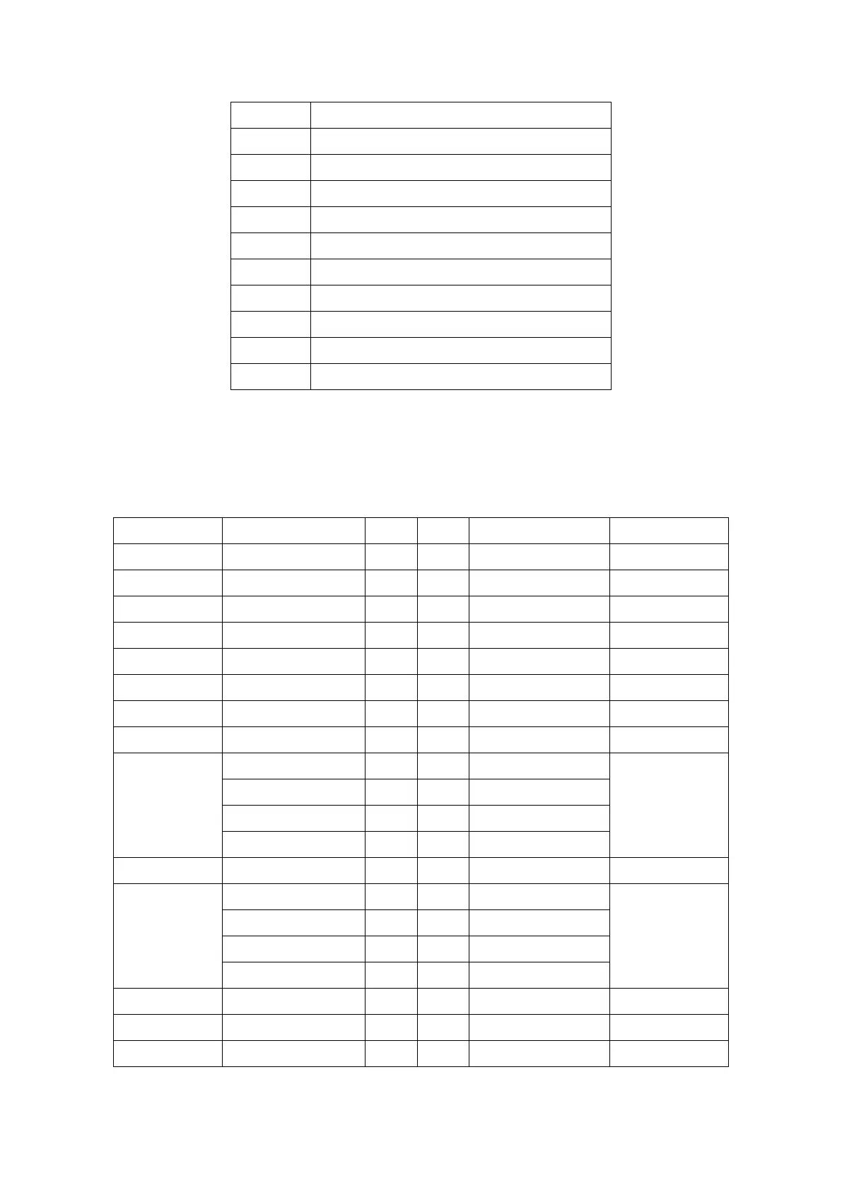
CN3
:
(1.27mm Pitch 2X30 Female Header), for expand output connector, it provides
four GPIO, two USB 2.0,one PS/2 mouse, one PS/2 keyboard, two uart,
one
PCIex1, one SMbus. connected to the TB-528 riser Card.
Function
Signal Name
Pin#
Pin#
Signal Name
Function
5V_S5_USB
1
2
5V
_S5_USB
5V_S5_USB
3
4
5V_S5_USB
USB1011_OC
5
6
PSON_A
T
X
-
E-USB10
E_USB10_N
7
8
E_USB10_P
E-USB10
E-USB11
E_USB11_N
9
10
E_USB11_P
E-USB11
Ground
11
12
Ground
PS/
2 MS
PS2_MSCLK
13
14
PS2_MSDA
T
A
PS/
2 MS
PS/
2 KB
PS2_KBCLK
15
16
PS2_KBDA
T
A
PS/
2 KB
COM4
(U
ART)
COM4_RI
17
18
COM4_DCD-
COM4
(U
ART)
COM4_TXD
19
20
COM4_RXD
COM4_DTR
21
22
RICOM4_R
TS
-
COM4_DSR
23
24
COM_CTS-
Ground
25
26
Ground
COM3
(U
ART)
COM3_RI
27
28
COM3_DCD-
COM3
(U
ART)
COM3_TXD
29
30
COM3_RXD
COM3_DTR
31
32
DSRCOM3_R
TS-
COM3_DSR
33
34
DTRC
OM3_CTS-
GPIO23
SO
C_GPIO23
35
36
ICH_GPIO22
GPIO12
GPIO25
SO
C_GPIO25
37
38
ICH_GPIO24
GPIO24
Ground
39
40
Ground
44
46
Table of Contents
Main Page
default chapter
2
Revision History
2
Warning!/Avertissement
3
Caution/Precaution/Disclaimer
4
Packing List
5
Safety Precautions/Consignes de Sécurité
6
Table of Contents
7
Features
9
Getting Started
9
Specifications
9
Dimensions
12
Figure 1.1: Dimensions of ARCHMI-807(P)
12
Figure 1.2: Dimensions of ARCHMI-808(P)
12
Figure 1.3: Dimensions of ARCHMI-810(P)
13
Figure 1.4: Dimensions of ARCHMI-812(P)
13
Figure 1.5: Dimensions of ARCHMI-815(P)
14
Figure 1.6: Dimensions of ARCHMI-816(P)
14
Figure 1.7: Dimensions of ARCHMI-817(P)
15
Figure 1.8: Dimensions of ARCHMI-818(P)
15
Figure 1.10: Dimensions of ARCHMI-821(Resistive Touch)
16
Figure 1.9: Dimensions of ARCHMI-819(P)
16
Brief Description of ARCHMI-8XX
18
Figure 1.12: Front View of ARCHMI-8XX Series
18
Figure 1.13: Rear View of ARCHMI-807/808
19
Figure 1.14: Rear View of ARCHMI-810
19
Figure 1.15: Rear View of ARCHMI-812
20
Figure 1.16: Rear View of ARCHMI-815
20
Figure 1.17: Rear View of ARCHMI-816
21
Figure 1.18: Rear View of ARCHMI-817
21
Figure 1.19: Rear View of ARCHMI-818
22
Figure 1.20: Rear View of ARCHMI-819
22
Figure 1.21: Rear View of ARCHMI-821
22
Installation of HDD - 7"/8
23
Installation of HDD - 10.1"/18.5
25
Installation of HDD - 12.1"/15"/15.6"/17"/19"/21.5
26
Figure 1.22: ARCHMI Series VESA Mounting
28
Figure 1.23: ARCHMI Series Panel Mounting
28
Panel Mounting
28
VESA Mounting
28
Chapter 2 Hardware
29
Motherboard Introduction
29
Specifications
29
Figure 2.1: Motherboard Dimensions
32
Jumpers and Connectors Location
33
Figure 2.2: Jumpers and Connectors Location-Board Top
33
Figure 2.3: Jumpers and Connectors Location-Board Bottom
33
Jumpers Setting and Connectors
34
BIOS Setup
47
Operations after POST Screen
47
BIOS Setup Utility
47
Main Settings
48
Advanced Settings
49
Chipset Settings
57
Security Settings
59
Boot Settings
60
Save & Exit Settings
61
Chapter 4 Installation of Drivers
63
Intel(R) Atomtm Soc Chipset
64
Intel(R) VGA Chipset
67
Intel(R) LAN Driver
71
Realtek ALC662 HD Audio Driver Installation
74
USB 3.0 Driver
75
Com Driver
78
Chapter 5 Touch Screen Installation
81
Windows Xp/2003/Vista/7 Universal Driver Installation for Penmount 6000 Series
81
Software Functions
91
Related product manuals
Aplex ARCHMI-8 Series
111 pages
 Loading...