Mixer Pane
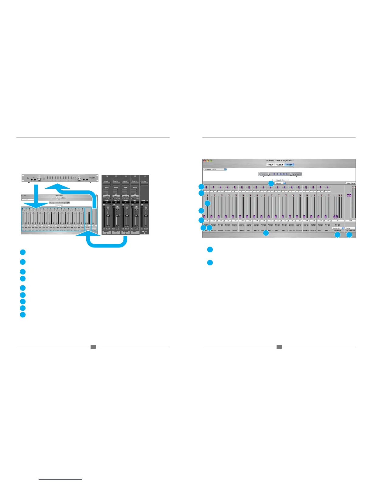
As described in the previous section, the Maestro mixer serves to blend hardware inputs with software outputs (playback),
and route the mix directly to hardware outputs, as depicted below.
1. Mixer Select (A-B) – This drop down menu selects between the two available mixers per hardware interface. (Note
that Duet offers only one mixer, thus the Mixer Select (A-B) drop down menu doesn’t appear when Duet is selected.)
2. Input channels – Hardware inputs of the selected interface (under the Interface menu) are the source for the Mae-
stro mixer inputs.
3. Pan – This slider pans the input signal between the left and right sides of the Maestro mixer output.
4. Pan value window – The pan value (where full left is designated <64, center is <0> and full right is 64>) is displayed
in this window.
5. Level fader – This slider set the level at which the input signal is mixed to the Maestro mixer output.
6. Level value window – The Level value (between “Muted” and +6) is displayed in this window
7. Meter – This bargraph style meter displays the pre-fader input level.
8. Mute – This button mutes the input channel.
9. Solo – This button solos the input channel, thereby muting all channels whose Solo buttons are not engaged.
Maestro Mixer Window Maestro Mixer Window
10. From Mac – This stereo input channel provides level control, metering and mute/solo functions for the signal from
the software application containing playback . Match the software application’s mixer output and the From Mac drop
down menu selection. In most cases the software mixer output and From Mac are both set to outputs 1-2.
11. To Hardware – This stereo output channel provides a level fader, metering and a routing drop down menu for control-
ling the stereo output of the Maestro mixer. Select the hardware output at which the Maestro mixer output should
appear. Again, in most cases To Hardware is set to hardware outputs 1-2
If To Hardware is set to None, the Maestro mixer is removed from the signal path, and the connection between the
software and hardware output is determined in the Output routing pane. When To Hardware is set to any hardware
output, the resulting routing is displayed in the Output pane as Mixer Out.
(Symphony PCI only) Maestro mixing may be accomplished from any hardware input to any hardware output as long as
the hardware is connected to the same Symphony PCI card.
For example, in a system that consists of an AD16X and DA16X connected to Symphony PCI card #1 and a Rosetta
800 connected to Symphony PCI card #2, any AD16X input may be mixed to any DA16X output, any Rosetta 800
input may be mixed to any Rosetta 800 output, but the AD16X inputs may not be mixed to the Rosetta 800 outputs.
1
2
3
4
5
6
7
8
9
10
11
1
2
3
4
5
6
7
8 9
10 11