2
INTRODUCTION
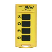
The APOLLO is a high quality, industrial grade remote control system, available in model formats from 4 to 12 functions.
Featuring a dust, water and oil resistant casing the APOLLO transmitter will also resist most impacts and extreme weather conditions.
Receiver box components have been placed into a tough control box with IP65 protection for your piece of mind.
MODEL OPTIONS
buttons, w/ EMS stop button
buttons, w/ EMS stop button
buttons, w/ EMS stop button
buttons, w/ EMS stop button
buttons, w/ EMS stop button
TECHNICAL SPECIFICATIONS
Frequency range: 868 or 433MHz ( 20 channels )
Channel spacing: 50KHz , 60KHz
Transmitting power: < 10mW ( 10dBm )
Antenna: Internal type, impedance as 50Ω
Security codes: 256 sets
Operation temperature: -10°C ~ +70°C
Enclosure: IP65
Source voltage: 4xAA ( 1.5V )alkaline batteries
or nickel rechargeable batteries
Consumption: < 7mA
Size: 217×70×49 mm (C1-6PB )
Frequency range: 868 or 433MHz ( 20 channels )
Channel spacing: 50KHz , 60KHz
Antenna: Internal type, impedance as 50Ω
Operation temperature: -10°C ~ +70°C
Enclosure: IP65
Source voltage: 9-30 volt Consumption: < 12W
Size: 250×120×75 mm ( C1-6PB )
Weight: 1080g ( C1-6PB )
INSTALLATION INSTRUCTIONS
Note 1: As the end use and positioning of the receiver unit can not necessarily be foreseen and the receiver may be
exposed to pressurised moisture in the form of waterblasting, road spray or similar the receiver should be mounted
inside a IP65 rated PDL style electrical enclosure or similar. Failure to mount the receiver unit in this manner may void
warranty of the system.
Note 2 : The power supply to the Apollo receiver unit must be fitted with an isolating switch for safety
APOLLO system installation should be a relatively straight forward procedure requiring a minimum of the following tools.
Long nose pliers, Side cutters, Philips head screwdriver, Multimeter and electric drill.
Steps:
(a) Ensure your existing machinery wiring is correct and fully operational prior to proceeding with a wireless system install.
(b) Ensure the receiver enclosure is mounted away from motors, relays, cables and high voltage wiring.
Preferably ensure the receiver mounting location is free of metal shielding / boxes or metal shielding protruding between your receiver
and the intended work area.
(c)
Do not install an APOLLO system with the same channel transmitter within 50 meters of an existing system.