32
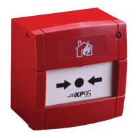
The XP95 Manual Call Point (EN54) is a ‘type A’ call point and is suitable for indoor use
only. For fl ush mounting, a suitable single-gang mounting box (minimum 20mm depth) is
required. XP95 glasses are also available, part no. 26729-154 (pack of 5)
Wiring Details
All wiring terminals accept solid or stranded cables up to 2.5mm².
Address Setting
The address of the Manual Call Point is set using the DIL switch. All segments of the switch
are set to 0 or 1, using a small screwdriver or similar tool.
A complete list of address settings is shown in the following table.
DIL switch DIL switch DIL switch DIL switch DIL switch
setting setting setting setting setting
addr 1234567 addr 1234567 addr 1234567 addr 1234567 addr 1234567
1 1000000 11 1101000 21 1010100 31 1111100 41 1001010
2 0100000 12 0011000 22 0110100 32 0000010 42 0101010
3 1100000 13 1011000 23 1110100 33 1000010 43 1101010
4 0010000 14 0111000 24 0001100 34 0100010 44 0011010
5 1010000 15 1111000 25 1001100 35 1100010 45 1011010
6 0110000 16 0000100 26 0101100 36 0010010 46 0111010
7 1110000 17 1000100 27 1101100 37 1010010 47 1111010
8 0001000 18 0100100 28 0011100 38 0110010 48 0000110
9 1001000 19 1100100 29 1011100 39 1110010 49 1000110
10 0101000 20 0010100 30 0111100 40 0001010 50 0100110
51 1100110 61 1011110 71 1110001 81 1000101 91 1101101
52 0010110 62 0111110 72 0001001 82 0100101 92 0011101
53 1010110 63 1111110 73 1001001 83 1100101 93 1011101
54 0110110 64 0000001 74 0101001 84 0010101 94 0111101
55 1110110 65 1000001 75 1101001 85 1010101 95 1111101
56 0001110 66 0100001 76 0011001 86 0110101 96 0000011
57 1001110 67 1100001 77 1011001 87 1110101 97 1000011
58 0101110 68 0010001 78 0111001 88 0001101 98 0100011
59 1101110 69 1010001 79 1111001 89 1001101 99 1100011
60 0011110 70 0110001 80 0000101 90 0101101 100 0010011
101 1010011 106 0101011 111 1111011 116 0010111 121 1001111
102 0110011 107 1101011 112 0000111 117 1010111 122 0101111
103 1110011 108 0011011 113 1000111 118 0110111 123 1101111
104 0001011 109 1011011 114 0100111 119 1110111 124 0011111
105 1001011 110 0111011 115 1100111 120 0001111 125 1011111
126 0111111
The switch in Fig 4 shows address setting 78 as an example of how to set the address
Commissioning
The installation must conform to BS5839–1: 2001 (or applicable local codes).
Ensure that a glass or deformable element is fi tted to each call point before testing. Use the
test key provided to check the operation of each device. An XP95 Test Set, part no. 55000-
870, may be used to carry out functional testing of individual units. The test set can also
perform data integrity tests of an entire system.
Note: the test key must remain inserted for at least 2 seconds to ensure the correct CIE
response.
Maximum Loop Current Consumption at 24V
typical switch-on surge, 2s typical 750μA
quiescent and alarm 100μA
LED illuminated 4mA
LED Indicator
~ Illuminated red (under CIE control) when call point is operated
~ Illuminated yellow when short-circuit isolator has operated (version with integrated
isolator)
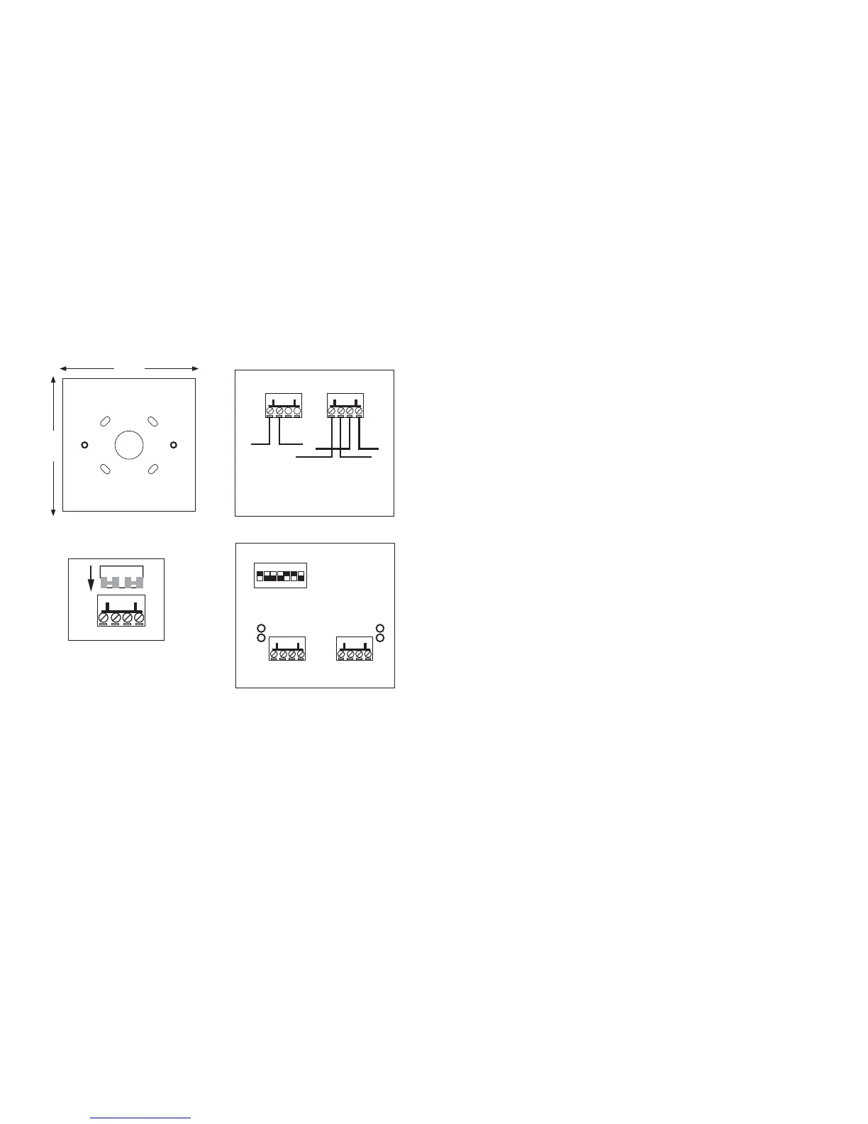
Terminals for
functional
earth/screen
connections
L+ L+ L– L–
Loop connections
Fig 2 Terminal block connections
Fig 4 Terminal blocks fi tted and
address 78 set
Fig 3 Continuity link
Fig 1 Backbox
87mm
87mm
1 234567
ON
0
1
 Loading...