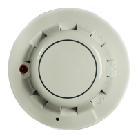
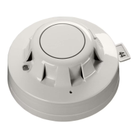
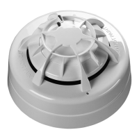
XP95A and Discovery Smoke & Heat Detectors
Installation Instructions
General
These instructions apply to Apollo detector base 45681-210, to variants of this base and to
the associated ranges of UL listed XP95A and Discovery detectors which are listed overleaf.
Installation
These products must be installed in accordance with the applicable NFPA standards, local
codes and jurisdictional authorities. Failure to follow these instructions may result in failure
of the detectors to report an alarm condition. Apollo Fire Detectors Limited is not responsi-
ble for detectors which are improperly installed, maintained and tested.
The FM approval for these initiating devices does not include or imply approval of the
control unit to which it may be connected. In order to maintain an FM approved system,
these initiating devices must be listed with an FM approved compatible control panel. For
more information on RTI classifi cation refer to FM class standard 3210.
Before installing these products check the continuity, polarity and insulation resistance of all
wiring. Check that installation is in accordance with the fi re system drawings and conforms
to all applicable local codes such as NFPA 72.
Use 3" octagonal box for direct connection to the base. 4" octagonal and 4" square boxes
may be used with proper UL listed mounting brackets. When mounting on a wall, install 4" to
12" from the ceiling. Use 3M Weatherban 606 Non-Flammable sealing compound (or equiv-
alent) to seal fi eld wiring conduit opening in the electrical box, this will reduce the stack
effect. Secure the base to the electrical box with appropriate screws. Do not overtighten
the screws. The raised mark on the side of the base indicates the direction of the detec-
tor LED when fi tted. Connect the shield, if required, to the SHIELD terminal on the base. For
information on how to set the address of each device correctly refer to the section 'Address
Setting' overleaf.
39214-035/Issue 11
Technical Data XP95A
Technical Data Discovery
14
Detector Model No. 55000-450 55000-550/555* 55000-650 55000-886
Detector Type Heat Ionization Photoelectric Multisensor
Working Voltage 17-28V dc 17-28V dc 17-28V dc 17-28V dc
Modulation Voltage
(V peak to peak)
5-9V 5-9V 5-9V 5-9V
Maximum Alarm
Current LED on
2.5mA 2.5mA 4.5mA 3.5mA
Surge Current 1.0 mA 1.0 mA 1.0 mA 1.0mA
Supervisory Current 250μA280μA340μA500μA
Heat Element Rating 131ºF (55ºC) N/A N/A N/A
Compatibility Identifi er 55000-450 55000-550/555* 55000-650 55000-886
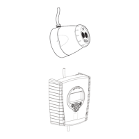
Test Method •Hair dryer •Home safeguard
•Gemini 501
•Home safeguard
•Gemini 501
•Home safeguard
•Gemini 501
Control Panel Refer to: www.apollo-fi re.co.uk for compatible panels.
*Please note 55000-555 is ULC listed only.
Detector Model No. 58000-450 58000-550 58000-650 58000-750
Detector Type Heat Ionization Photoelectric Multisensor
Working Voltage 17-28V dc 17-28V dc 17-28V dc 17-28V dc
Modulation Voltage
(V peak to peak)
5-9V dc 5-9V dc 5-9V dc 5-9V dc
Maximum Alarm
Current LED on
3.5mA 3.5mA 3.5mA 3.5mA
Surge Current 1.0 mA 1.0 mA 1.0mA 1.0mA
Supervisory Current 500μA400μA500μA500μA
Heat Element Rating 135ºF (57ºC)
-210ºF (99ºC)
N/A N/A 135ºF (57ºC)
(Mode 5)
Compatibility Identifi er 58000-450 58000-550 58000-650 58000-750
Test Method •Hair dryer •Home safeguard
•Sensitivity test
•No Climb
•Gemini 501
•Home safeguard
•Sensitivity test
•No Climb
•Gemini 501
•Home safeguard
•Sensitivity test
•No Climb
•Gemini 501
•Hair dryer (heat
sensor only)
Control Panel Refer to: www.apollo-fi re.co-uk for compatible panels.
©Apollo Fire Detectors Ltd 2017
Apollo Fire Detectors Ltd, 36 Brookside Road, Havant, Hants, PO9 1JR, UK
Tel +44 (0)23 9249 2412 Fax +44 (0)23 9249 2754
Email: techsales@apollo-fi re.com Website: www.apollo-fi re.co.uk
In the USA: Apollo America Inc., 25 Corporate Drive, Auburn Hills, Michigan, 48326, USA
Tel: (248) 332-3900 Fax: (248) 692-0888
Email: info.us@apollo-fi re.com Website: www.apollo-fi re.com