103N / 105N / 106
EN
1-3 Front Panel
Refer to Figure 1 and to the following numbered steps to
familiarize yourself with the meter’s front panel controls and
connectors.
1. Digital Display — The digital display has a 4000 counts
LCD readout with 82 segments analog bar graph, auto
polarity, decimal point, “
“ AC, DC, , , RANGE,
H
,
APO, REL, MAX, MIN, PMAX, PMIN and unit
annunciators. (PMAX, PMIN, REL are 105N / 106 only).
2. Rotary Switch — Select the Function and Range
desired.
3. COM Input Terminal — Ground input connector.
4. °C °F
VΩ Hz Input Terminal — Positive input
connector for Volts, Ohms Capacitance, Frequency and
Temperature.
5. mA Input Terminal — Positive input connector for Amp
measurements (up to 400mA).
6. A Input Terminal — Positive input connector for Amp
measurements (up to 10A).
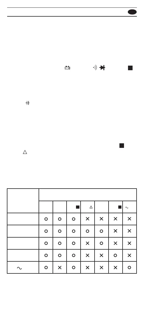
Push Switch Functions ( “MIN/MAX” and “Peak
H
” and
“Rel
“ switch are for 105N / 106 only)
Push switch functions control the special measurement
modes of the meter. Some special modes can be nested
in other special modes, while some push functions reset
all existing special mode. The following table summarizes
the push functions in each special mode.
HOLD
Active mode
Push Switch Functions
RANGE
1
Hz
2
BLUE
KEY
1
MIN/
MAX
HOLD
H
PEAK
H
REL
REL
MIN/MAX HOLD
PEAK HOLD
HZ
 Loading...