CSPP Capacitor Charging Unit Operation Manual
_________________________________________________________________________________________________________
__________________________________________________________________________________________________________
Page 31 of 59
3. High Voltage On Circuit
The high voltage can be activated from the power supply front panel, or remotely from the
instrument room using the remote box and cable. Both switches are controlled using the Remote /
Local (R/L) switch on the front panel.
With the switch in local the high voltage can only be operated from the power supply front panel,
disabling the remote HV ON button.
If the R/L switch is in remote, the power supply can only be operated from the instrument room,
also disabling the front panel HV ON button. The high voltage OFF button will still operate
regardless either from the front panel or on the remote box if pressed.
The HV ON switch is connected to IC5D on the control board. Providing there is no fault condition,
RS latch IC5 is set, sending its O/P high. The 8 input OR gate IC6 also has a NOR function Pin
13. With no faults or resets (logic 1s) on the I/P, the NOR O/P on Pin 13 will be high sending the
O/P of AND gate 11D high. This will then allow any high voltage capacitors to be switched in
circuit via the HV relay control circuit.
IC7B is also triggered, generating a 3 second delay before the high voltage from the charger is
activated.
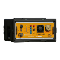
Front Panel Board
Drawing No CSP1000-5004 Section 3.
The front panel (FP) board contains driver circuits for LEDs on the CSP front panel. Most of the
panel switches are connected to the control board via the FP board.
The HIGH VOLTAGE ON and EOC (End Of Charge) LED inputs, are controlled directly from the
Charger. OP1/2 provide isolation between the FP board and the charger.
The output power switch is monitored by a reset circuit comprising IC1 (4 I/P OR gate) and IC2
(RS latch). Whenever the O/P power switch is operated, one of the inputs to IC4 will go high,
sending the output high and setting the RS latch. The output is connected to the HV OFF / RESET
circuit on the control board, which will then reset the CSP power supply.