CIRCUIT. HOWEVER, THE TRANSFORMER CAN BE POWERED OFF
THE HOT 120 VAC LINE BEFORE IT ENTERS THE FURNACE.
PRIMARY CIRCUIT.
INTO FURNACE BLOWER CIRCUIT.
24V ACTIVATED WITH HEAT CALL.
OPERATION PARAMETERS OF ACCESSORY TERMINALS.
INSTALLATION OPTIONS
Typical Installation Alternate Installation
COOLING COILS IN
WARM AIR PLENUM
Aprilaire to
be installed
as shown in
relation to
cooling coils.
RECOMMENDED WIRING DIAGRAMS
(SEE STEP 6 ON BACK AND “HUMIDIFIER CONTROL SAFETY AND INSTALLATION INSTRUCTIONS” FOR DETAILED WIRING INSTRUCTIONS)
90-1206
90-1208
90-922
90-921
RETURN
RETURN
HOT WATER
SUPPLY
SUPPLY
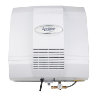
Orientation of Aprilaire Model 700M
and 700A to Cooling Coils
WARNING
1. ELECTRICAL SHOCK HAZARD.
Disconnect electrical power to the
furnace before starting installation.
Failure to do so could result in serious
injury from electrical shock.
2.
SHARP EDGES HAZARD. Sharp
edges may cause serious injury from cuts.
Use care when making plenum openings
and handling ductwork.
3.
RISK OF SCALDING. Water
temperature over 125°F can cause severe
burns and scald instantly. Shut off the hot
water supply before disconnecting or
tapping into any hot water supply line.
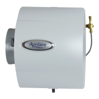
SPECIFICATIONS
HUMIDIFIER DIMENSIONS
Width 15
29
⁄32”
Height
(including solenoid valve
and drain spud)
18”
Depth 10
11
⁄32”
PLENUM OPENING
14
3
⁄4”W x 14
5
⁄16”H
WATER FEED RATE
6 gph
ELECTRICAL DATA
120 VAC-60 Hz, 0.8 AMP
CAUTION
1. Do not install humidifier where freezing temperatures
could occur. The water line could freeze and crack
causing water damage to the home.
2. Do not install humidifier on the furnace jacket.
3. Do not install humidifier on a plenum face where the
blanked off ends of the cooling coil will restrict air
movement through the humidifier.
4. Do not set humidity level above recommended or to
recommended level if condensation exists on inside
windows of any unheated space, as condensation
damage may result. Excess humidity can cause
moisture accumulation which can allow the possibility
for mold growth in the home.
5. Do not connect the Model 700M or 700A power cord to multi-
speed furnace blower motors or blower motors other than 120
VAC. Premature component failure may result. Use Research
Products Corporation Model 50 Current Sensing Relay.
6. When installing Aprilaire Humidifier Control on a downflow
furnace, ensure blower continues to run after a heat call is
satisfied to eliminate high temperatures from damaging the
Control.
7. Do not install humidifier where water pressure exceeds
125 psi, since damage to the humidifier may result. Follow
codes in effect concerning pressure reduction.
8. Do not install humidifier on the supply plenum where static
pressure exceeds 0.4 in. wg.
RISK OF PROPERTY AND EQUIPMENT DAMAGE.
BLANKED OFF
END OF COIL
NOTES
1. Models 700M and 700A
are not suitable for
installation on ducts
with horizontal airflow.
Performance will be
reduced.
2. When installing Aprilaire
humidifier on a heat
pump system, use hot
water. The heated
water supplements the
reduced supply air
temperature as added
heat for evaporation.
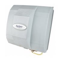
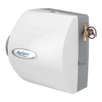
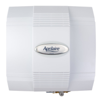
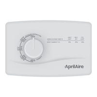
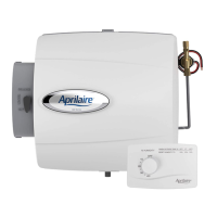
Model 700M
MANUAL CONTROL
Model 700A
AUTOMATIC DIGITAL
HUMIDIFIER CONTROL