ETV mille
ELECTRICAL SYSTEM
6
- 9 - 00Release 00/2004 - 04
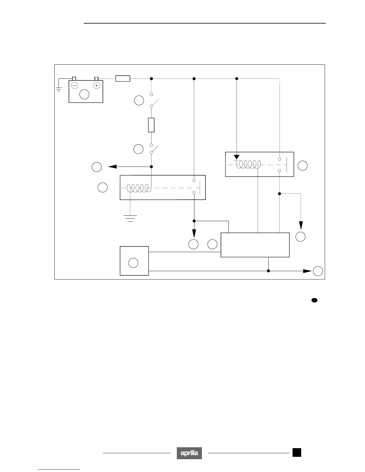
6.4 INJECTION SYSTEM
6.4.1 INJECTION SUPPLY WIRING DIAGRAM
Key:
1) Battery
2) Key-operated switch
3) Kill switch
4) Starter button
5) Engine cutout relay
6) Injection relay
7) Bank angle sensor
8) Power supply to injectors, fans, coils, purge valve
9) ECU
10) To fuel pump relay
11) Throttle position sensor, thermistors
6.4.2 TROUBLESHOOTING
! Check that the 30-A main fuse and the 15-A fuse ≈D∆
are in good condition.
! Test kill switch device operation, see 6.8 (SAFETY
LOCKOUT SYSTEM). Test key-operated switch
operation, see 6.5 (IGNITION/INJECTION SYSTEM).
! Test the engine cutout relay for proper operation,
see 6.7.3 (TEST OF FUEL PUMP RELAY AND
ENGINE CUTOUT RELAY).
! Test the injection relay, see 6.4.3 (INJECTION RELAY
TEST).
! Test the bank angle sensor, see 6.4.4 (BANK ANGLE
SENSOR TEST).
30A
R/Bi
D
15A
Az/Gr
Ro/Bi
E1
(Grey)
F3
(Grey)
H4
(Black)
B3(Grey)
E4(Black)
N
R/M
Ro/Bi
B/R
2
1
3
4
5
7
6
8
910
11
USA

 Loading...