CHASSIS
7 -54
Pegaso 650 I.E.
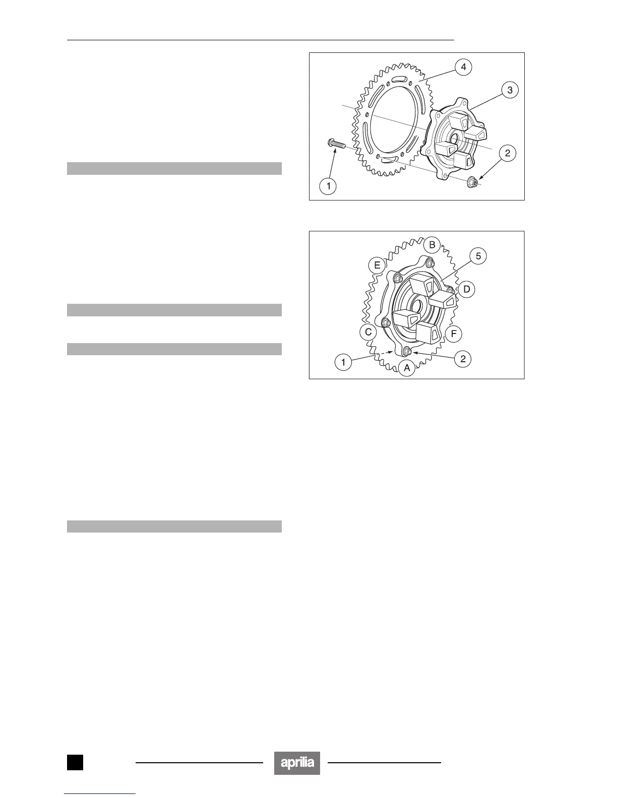
7.3.17 REMOVING THE CROWN GEAR
Carefully read 0.5.1 (PRECAUTIONS AND GENERAL
INFORMATIONS).
◆ Remove the final drive unit, see 7.3.2 (REMOVING
THE FINAL DRIVE UNIT).
◆ Lock the rotation of the screw (1), unscrew and remove
the six self-locking nuts (2).
Crown gear self-locking nut driving torque: 50 Nm
(5.0 kgm).
aCAUTION
The self-locking nuts (2) must be replaced on each
removal of the crown gear.
Replace the self-locking nuts (2) with nuts of the
same type.
◆ Remove the crown holder (3).
◆ Clean the crown gear (4) and the crown holder (3) with
clean detergent.
Reassembly:
◆ Insert the six screws (2) in the crown gear (4).
◆ Install the crown holder on the crown unit.
◆ Screw the six self-locking nuts (2) manually.
aCAUTION
It is forbidden to install the final drive unit (5) on the
wheel to tighten the self-locking nuts.
aCAUTION
To protect the crown gear, install guards (in wood or
aluminium) on the vice jaws. Lock only the crown
gear in the vice, be careful not to lock any other com-
ponent of the final drive unit.
◆ Lock the crown gear in the vice.
NOTE To avoid any deformation and/or incorrect cou-
pling, carry out the tightening as described below:
◆ Lock the rotation of the screw (1) and tighten the self-
locking nuts (2) in the given order, applying half the pre-
scribed driving torque: (A) (B) (C) (D) (E) (F).
◆ Repeat the previous operation by applying the pre-
scribed driving torque.
NOTE In this way the pressure exerted by the fasten-
ing elements will be uniformly distributed on the joint sur-
face.
aCAUTION
Check the wear of the flexible coupling rubber ele-
ments and if they are worn replace them with new
ones of the same type.
Release 00/2002-02
- 00
 Loading...