5609 RS 01/17
PAGE 16
©2017 4Front Engineered Solutions, Inc. - APS Resource
1
1
2
2
3
3
4
4
A A
B B
C C
D D
- CRITICAL QUALITY DIMENSION
TOLERANCES ARE IN INCHES
UNLESS OTHERWISE SPECIFIED
MATERIAL SPECIFICATION
DRAWN
MATERIAL#/PO#
PART DESCRIPTION
DRAWN DATE
JOB/REF NUMBERSCALE
ISSUEPART NUMBER
.X :
0.060
.XX :
0.030
.XXX :
0.010
FRACTIONAL :
1/16
DIAMETER : +0.015 / -0.005
ANGULAR :
1 DEG
AFORM5609-FIG16
APS 2000 SUB-ASSEMBLY
NONE
JJS 2/29/2012
UOM
INCH
The information contained herein is proprietary and confidential to 4Front Engineered Solutions, Inc. - APS Resource and is to be
used solely for the express purpose of consideration and development of the article described herein and may not be reproduced or
disseminated without the express written permission of 4Front Engineered Solutions, Inc. - APS Resource.
SHEET SHEET SIZE
C1 OF1
Your Afterma rket So lution
APS Resource
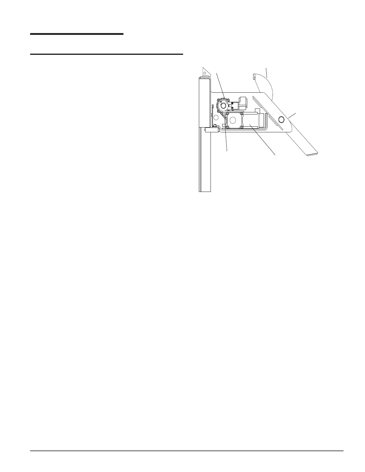
PLANNED MAINTENANCE
CHAIN ADJUSTMENT PROCEDURE
1. Move the hook to horizontal position and remove
motor cover. See Figure 18.
2. Check the drive chain slack. It should not have more
than 1/4" slack. See Figure 18.
3. If the chain needs adjustment, loosen the three nuts
on the motor mounting carriage bolts and move the
motor toward the front of the carriage. Make sure the
sprockets are in line and tighten the mounting bolts.
Recheck the slack in the chain. See Figure 18.
4. Reinstall the motor cover.
5. Turn power on and press "RELEASE" push-button to
store the hook.
FIGURE 18
MOTOR
FRONT OF
CARRIAGE
SLACK 1/8" - 1/4"
CHAIN
CHECK WITH HOOK IN
HORIZONTAL POSITION