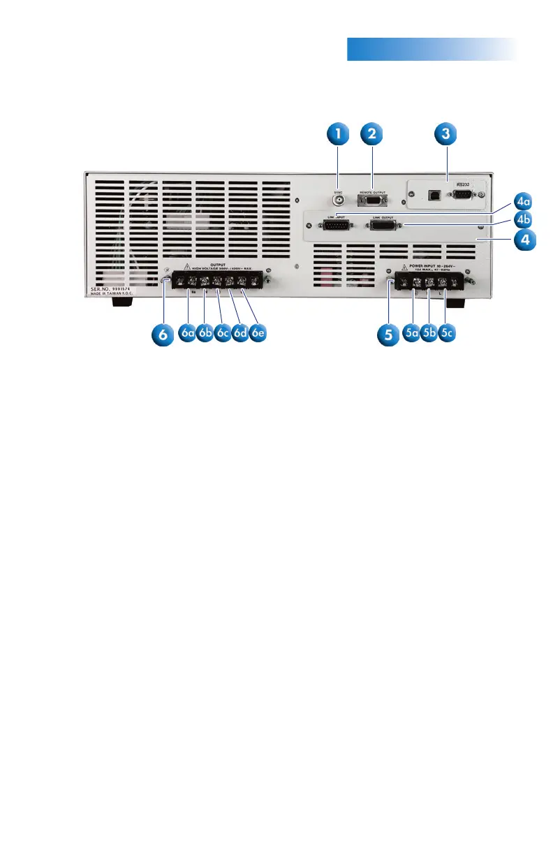
BACKPANELCONTROLS
2.
1. SYNC OUTPUT CONNECTOR: Provides the capability to monitor a 5 VDC output
signal.
2. REMOTE OUTPUT CONNECTOR: Provides output to monitor PASS, FAIL,
Test-In-Process via relay contact closures.
3. AUTOMATED INTERFACE CARD: Interface card used to control, program, and
capture data.
4. LINKING CARD (OPT. 8): Provides input and output communication ports for
operating multiple instruments in parallel and polyphase modes.
4a. Interface Input: Connector used to attach the instrument to a master power
source. Connecting the interface cable to this port automatically designates the
instrument as a slave unit.
4b. Interface Output: Connector used to attach the instrument to a slave power
source. Connecting the interface cable to this port automatically designates the
instrument as a master unless an interface cable is also connected to the Interface
Input port (in this case the instrument is automatically configured as a slave).
5. INPUT TERMINAL POWER BLOCK: Provides input power to the instrument.
Models 310XAC and 320XAC require 90-264 VAC 1Ø, 47-63 Hz.
5a. G: Earth ground (chassis) connection.
5b. N: Neutral input screw terminal.
5c. L: Line input screw terminal.
6. OUTPUT TERMINAL POWER BLOCK: Provides output power to the DUT.
6a. Ns: Neutral sense screw terminal.
6b. N: Neutral output screw terminal.
6c. G: Earth ground (chassis) connection.
6d. L: Line output screw terminal.
6e. Ls: Line voltage sense screw terminal.
 Loading...