Do you have a question about the APT 320XAC and is the answer not in the manual?
Lists safety and EMC standards the product complies with.
Details compliance with Low Voltage, EMC, and RoHS directives.
Details the product warranty terms, conditions, and coverage limitations.
Provides definitions for technical terms used in the manual.
Explains product marking and caution/warning symbols.
Outlines essential safety procedures and guidelines for operation.
Covers routine maintenance, cleaning, and service intervals.
Instructions for unpacking, inspecting the instrument, and safe handling.
Guidance on selecting appropriate wire gauges and power cable requirements.
Charts detailing the output current capabilities of each 300XAC model.
Information on the function and limitations of the instrument's power switch.
Table providing recommended wire gauges for input/output connections.
Details on power cord requirements and safety guidelines for connections.
Lists accessories supplied with the 360XAC model for input connections.
Specifies operating and storage environmental limits for the instrument.
Guidelines for packaging the instrument for return or shipping.
Detailed technical specifications for the 300XAC series AC power sources.
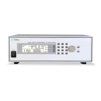
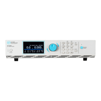
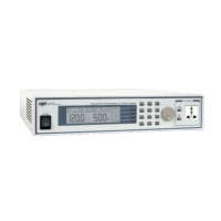
Overview of front and rear panel controls, including soft keys.
Step-by-step guide on powering on and navigating the initial screens.
Explanation of system parameters affecting overall instrument operation.
Procedures for modifying system parameters like Auto Run, Out Mode, etc.
Instructions on saving, recalling, and managing test memories and steps.
Explains the PROGRAM and MANUAL modes for test execution.
Steps to start a test sequence in PROGRAM mode.
Steps to start a test sequence in MANUAL mode.
Guide to setting up multiple 300XAC units for parallel or polyphase operation.
Procedures and considerations for powering up interconnected instruments.
Definition and behavior of the Over Temperature Protection message.
Definition and behavior of the Over Current Protection message.
Definition and behavior of the Over Power Protection message.
Definition and behavior of the Output Voltage Protection message.
Definition and behavior of the Amplifier Shutdown Protection message.
Definition and behavior of the Reverse Current Protection message.
Definition and behavior of the Low Voltage Protection message.
Definition and behavior of the LCD Temperature Protection message.
Describes remote monitoring signals via a 9-pin D-type connector.
Explains remote control of tests and memory recall using input interface.
Information on using the standard USB/RS-232 interface and driver installation.
Details on the optional GPIB interface and its configuration.
Explanation of GPIB interface functions and capabilities.
Comprehensive list of commands for remote control via USB, GPIB, and RS-232.
Steps for hardware verification and calibration if software fails.
Procedure to activate the non-calibration mode for adjustments.
Steps to adjust the control circuit power voltage.
Steps to adjust the amplifier inverter DC bus voltage.
Procedure to clear high frequency noise on specific models.
Steps to adjust DC offset for zero and 110V settings.
Procedure to adjust the wattmeter offset for accurate readings.
Steps to adjust the Over Current Protection (OCP) set point.
Procedure to exit non-calibration mode and return to normal operation.
Recommended procedure for software calibration after hardware checks.
Description of the Grounded Neutral option for reduced leakage current.
Details the GPIB interface card option.
Explains the option for remote recall of memory locations.
Information on the Ethernet Card, its ports, and setup.
Description of the Linking Card for instrument interconnection.
Guidelines for user safety and avoiding electrical shock.
Requirements for regular checking and calibration for accuracy and safety.
Discourages user modifications and explains warranty voidance.
| Brand | APT |
|---|---|
| Model | 320XAC |
| Category | AC Power Distribution |
| Language | English |