17
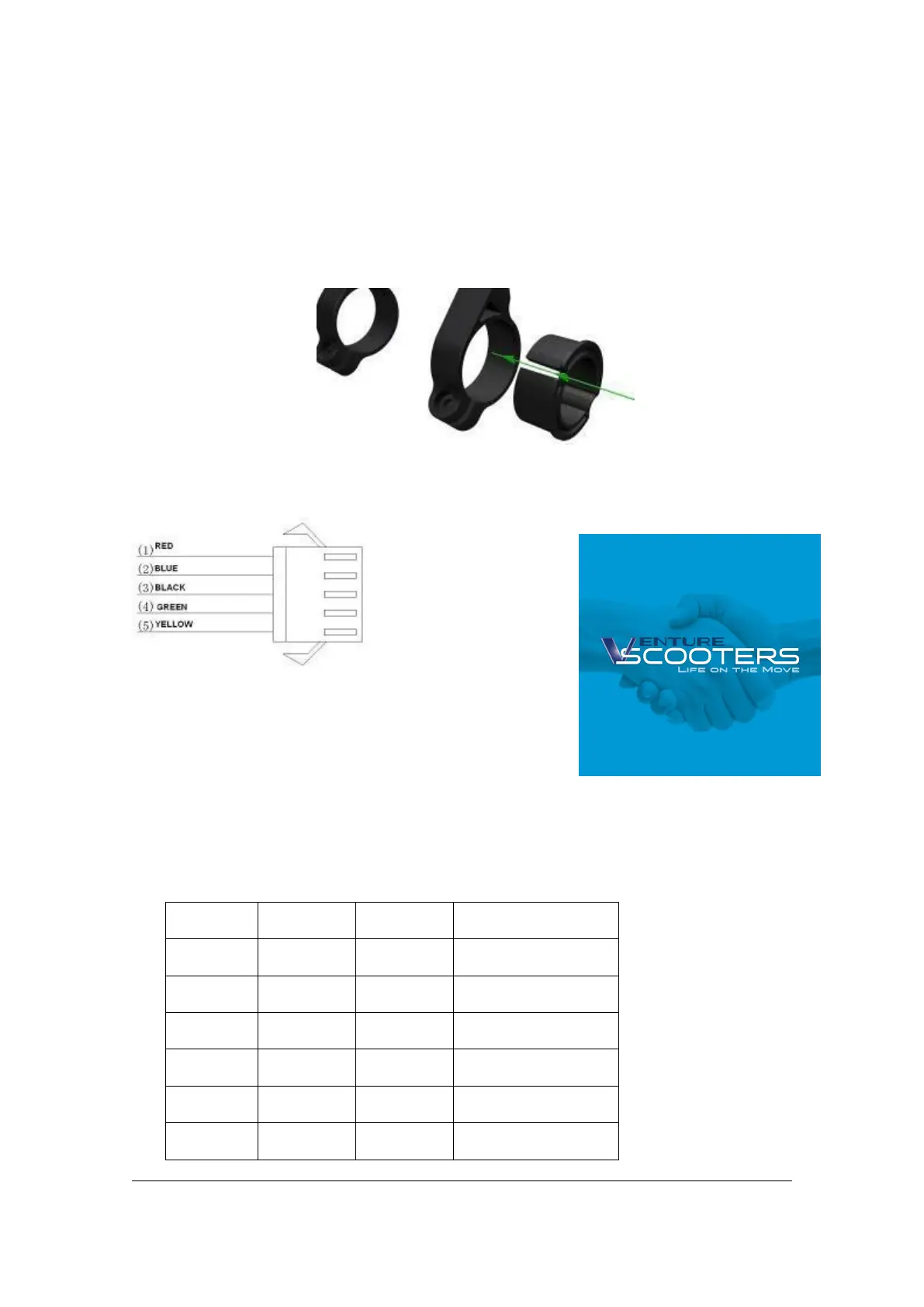
Clamps suit for 3 size of handlebar, 31.8mm, 25.4mm, 22.2mm, there are transfer rings for
25.4mm and 22.2mm, transfer ring must be assembled with the special directions, pay
attention to the green arrow below.
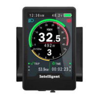
11. Connector descriptions
1、 Red wire : Anode(24v/36v/48V)
2、 Blue wire : Power cord to the controller
3、 Black wire : GND
4、 Green wire : RxD (controller -> display)
5、 Yellow wire : TxD (display -> controller)
12. Assist level instructions
Assist level can be customized, the highest level is 9, common used assist level see the
table below: