Do you have a question about the APT 860C and is the answer not in the manual?
Specifies the display type as a TFT LCD.
Identifies the product model number as 860C.
Lists the supplier company name.
Details the screen size and type.
Specifies compatible battery voltage options: 24V, 36V, 48V, 52V.
Includes rated, max operating, and leakage current specifications.
Defines the USB port's output specifications: 5V 500mA.
Indicates the maximum current output to the controller: 100mA.
Defines the operational (-20~70°C) and storage (-30~80°C) temperature ranges.
Details the materials used for the product shell (ABS+PC) and screen.
Provides the physical dimensions of the main unit: L96.6mm*W71.6mm*H6.1mm.
Highlights suitability for cold weather operation down to -20°C.
Emphasizes the quality of the 3.5-inch high-contrast colorful matrix screen.
Notes the user-friendly, easy-to-operate external button layout.
Lists available speed display modes: AVG SPEED, MAX SPEED, SPEED(Real-time).
Allows setting distance units (Kilometer/Mile) based on user habits.
Mentions an intelligent system for providing a reliable battery status.
Details the 9-level assist system with optional 3-level/5-level configurations.
Specifies the types of data displayed: Odometer, Trip distance, Clock, Riding time.
Indicates functionality for displaying real-time power or current.
Notes the presence of an indicator for displaying error codes.
Mentions an optional feature for a light sensor.
Explains that software can be upgraded via UART connection.
Confirms the USB port's charging capabilities: 5V/500mA.
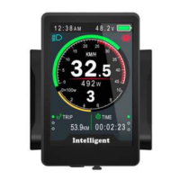
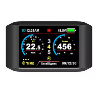
Indicates the display of the current time.
Shows the status of the front light.
Represents the power consumption or flow.
Visual representation of the speed gauge.
Displays the current power output.
Visual representation of the power gauge.
Shows accumulated distance or trip data.
Area for switching between different display modes.
Indicates the battery status.
Shows when the brake signal is active.
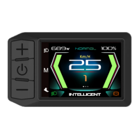
Displays the current speed numerically.
Shows the current power output.
Indicates the selected assist level.
Displays the duration of the ride or other time metrics.
Area for the product logo.
Instructions for turning the display on and off.
How to adjust the electric assist levels.
How to switch between different speed and mileage display modes.
Instructions for controlling the headlight and screen backlight.
How to activate the low-speed walking assistance mode.
Procedure for resetting temporary ride data.
Setting the display language; default is English and unadjustable.
Switching between Metric and Imperial measurement units.
Adjusting the screen backlight brightness level.
Configuring the automatic display power-off timer duration.
Setting the display scene mode, limited to analog.
Customizing the battery indicator display (Voltage, Percentage, OFF).
Setting the power indicator to show Power or Current.
Procedure for setting the device's date and time.
Setting and managing a startup password for the display.
Setting wheel diameter for accurate speed and distance readings.
Selecting the appropriate battery voltage for the system.
Enabling or disabling USB port power output.
Configuring the automatic light sensor and sensitivity levels.
Accessing advanced settings menu, requires a password.
Setting the maximum speed limit for the e-bike.
Customizing the number of available electric assist levels.
Function to view past error codes recorded by the system.
Restoring all settings to their original factory defaults.
Shows general information about the e-bike.
Displays hardware and software version details.
Provides comprehensive battery health and status data.
Throttle is stuck in a high position.
General throttle malfunction.
System protected due to high voltage.
Hall effect sensor failure in the motor.
Motor phase wiring issue.
Controller overheating.
Motor overheating.
Malfunction in the current sensor.
Battery temperature sensor failure.
Motor temperature sensor failure.
Controller temperature sensor fault.
Speed sensor malfunction.
Communication failure with the Battery Management System.
Headlight system error.
Headlight sensor malfunction.
Torque sensor reporting incorrect torque.
Torque sensor reporting incorrect speed.
General communication failure.
Details on screw torque specifications and handlebar clamp options.
Explains what each wire color signifies in the connector.
Brown wire is for battery anode connection (24V/36V/48V/52V).
Orange wire connects power to the controller.
Black wire is the ground connection (GND).
Green wire transmits data from controller to display (RxD).
White wire transmits data from display to controller (TxD).
Details on how assist levels can be customized.
Tables showing common assist level configurations (3, 5, 9 levels).
Lists product certifications for safety, water resistance, and materials.
This document describes the 860C TFT LCD display, a component designed for electric bikes, manufactured by APT (Tianjin) Develop Co., Ltd.
The 860C display serves as the primary interface for controlling and monitoring an electric bike. It provides real-time information about speed, mileage, battery status, power output, and assist level. Users can customize various settings, including speed limits, assist levels, and display preferences. The device also features error code indicators for troubleshooting and a walking mode for easy maneuvering at low speeds.
Power On/Off: To turn the display on or off, press and hold the "Power" button for 1 second. The display can be configured to automatically shut down after a set period (0-9 minutes) of inactivity. If a password is set for power-on, it must be entered before the device starts.
Assist Level Operation: The assist level can be changed by short pressing the "UP" or "DOWN" buttons. The top assist level is 9, with 0 representing neutral. The number of assist levels can be customized according to user requirements (e.g., 3, 5, or 9 levels).
Speed & Mileage Mode Switch: Pressing the "MENU" button allows users to cycle through different speed and mileage modes, including TRIP, ODO (Odometer), RANGE, TIME, MAX SPEED, and AVG SPEED.
Headlight/Backlight On/Off: Press and hold the "UP" button for 1 second to turn the headlight and backlight on or off. The screen will switch to the corresponding mode (daytime or night mode). The display can maintain the headlight function for a period even if the motor is not working due to low battery voltage.
Walking Mode (6km/h): To activate walking mode, press and hold the "DOWN" button for 2 seconds. Releasing the button exits this mode. This feature requires controller support.
Data Cleanup: Simultaneously pressing and holding the "UP" and "DOWN" buttons for 1 second will reset temporary data, including AVG Speed, MAX Speed, Trip distance, and Riding Time. These temporary data cannot be erased by powering off the device.
Parameter Setting: Double-pressing the "MENU" button (with an interval less than 0.3 seconds) enters the setting menus. "UP/DOWN" buttons change parameter settings, and the "MENU" button switches to the next item. Double-pressing "MENU" again exits the menu. The display automatically exits the menu after 30 seconds of inactivity or when riding starts. Parameters include:
Basic Setting Menu: Accessed by pressing the "DOWN" button to move the red arrow to "Basic Setting" and then pressing "POWER".
Advance Setting Menu: Accessed by pressing the "POWER" button within the "Basic Setting" menu. Default password is '1919'.
Factory Setting: Pressing the "MENU" button in the "Factory setting" item and selecting "YES" will restore all parameters to factory defaults.
Information: Displays E-bike information, including Speed (AVG, Max), Mileage (Trip, ODO, Range), Product Information (Hardware ver., Software ver., Date, Serial No), and Battery Information (Voltage, Current, Avg Current, Cycle times, Capacity, Remaining Capacity, Full Charge Capacity, Temperature, Max/Min Tempt, Relate/Absolute ChgSta, Max/Last Uncharge Times, CorVolt-1). Battery information requires battery communication support.
Error Code Definition: The 860C display shows warning messages with a "!" icon and error codes at the bottom of the screen. Error codes from 04 to 30 are defined in the manual, indicating issues such as throttle errors, voltage protection, motor sensor errors, temperature issues, and communication errors. This feature aids in diagnosing problems.
Assembly Instructions: Users are advised to pay attention to the screw's torque value during assembly, as damage caused by excessive torque is not covered under warranty. The clamps are suitable for 3 handlebar sizes (31.8mm, 25.4mm, 22.2mm), with transfer rings provided for 25.4mm and 22.2mm, which must be assembled in specific directions.