GB
Form no.: L453147GB– revision 06/2013
7. Service and maintenance
7.3 Replacing the motor
ThestandardmotoroftheW+pumphasalockedfrontbearing.
Ifthemotorisreplaced,thenewmotormustalsohavealocked
frontbearing.Themotorbearingisenclosedandpermanently
lubricated.
A"smallange"(B34)forframesizesanda"largeange"(B35)in
caseoflargeconstructions.
Whenreplacingthemotor,followtheinstructionsbelow.For
thereplacementofbearings,seethemotorsupplier'sservice
instructions.
1. Switchoffthepowersupply,andthendisconnectthepumpand
motorfromthesystem.
2. Remove the pump body. See 7.2, paragraph 1-4.
3. Dismantle the impeller.
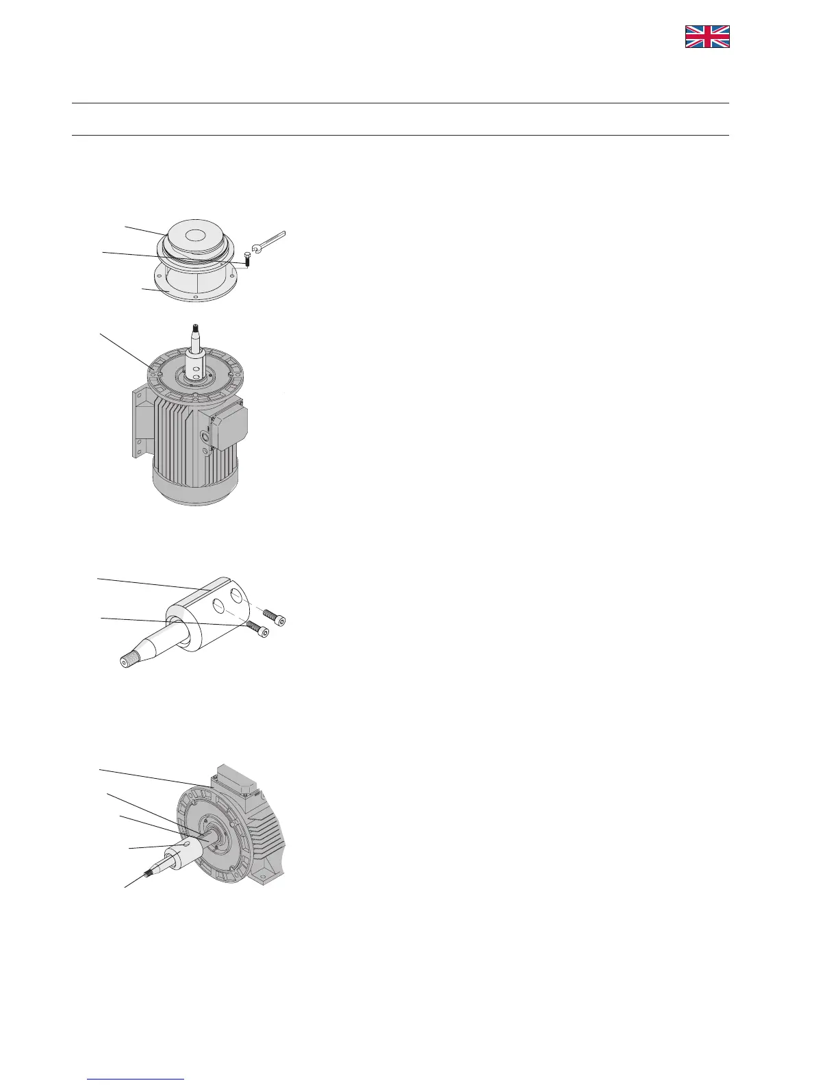
4. Removethemotorshroudand,ifpossible,placethepumpvertically
onthemotor'sfancover.Fig.7.
5. Releasethefourmotorangescrewsandremovethem(Fig.7).
6. Liftthebackplate(item7)andextensionframe(whicharestill
boltedtogether)offtheshaft.SeeFig.10.
Removethespacerange(item17)(wheretted).
7. SeeFig.8.Loosenthescrewsatthebaseoftheshaft,removethe
shaftandreplacethemotor.
8. SeeFig.9.Beforemountingthenewpumpshaft,removeanydirt
andgreasefromthemotorshaftandthebase'sinternalclamping
surfaces.Looselymountthepumpshaft.Positionthebalancehole
overthekeyway.
9. Fitthebackplateandextensionframeovertheshaft.
10. Tighten the bolts.
11. Standthepumpbackonitslegs/brackets.
12. Fittheimpellerandsecureitwiththecapnut/inducer.
Remember to use the proper tightening torque:
M10: 45Nm(33ft-lb)
M14: 70Nm(52ft-lb)
M20: 200Nm(148ft-lb)
Fig. 7
Fig. 8
Fig. 9
Rearange
Screw
Extensionframe
Motor
Shaft
Screw
Motor
Keyway
Motorshaft
Balancehole
Pumpshaft
13
APV