GB
Form no.: L453147GB– revision 06/2013
7. Service and maintenance
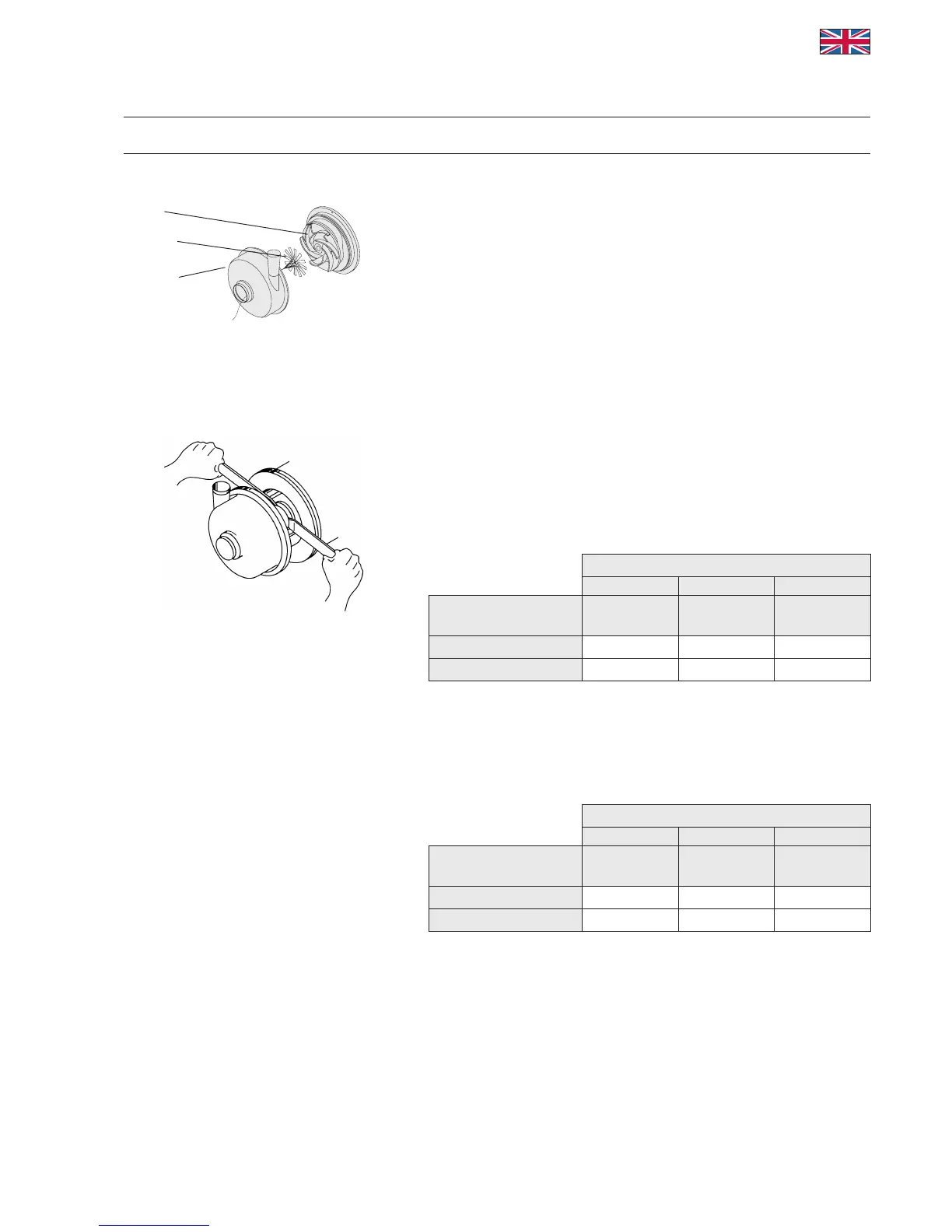
13. Placetheplasticstaragainsttheimpeller.Fig.10.
14. Fitthepump/screwhousingandfastenwiththeclampring.
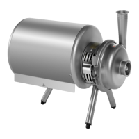
15. Pushtheshaftforwarduntiltheimpelleristouchingtheplasticstar.
See Fig. 11.
16. Tightentheshaftscrews(item11).
Remember to use the proper tightening torque:
M8: 30Nm(22ft-lb)
M10: 55Nm(41ft-lb)
M12: 80Nm(59ft-lb)
M16: 180Nm(132ft-lb)
17. Remove the star by pulling it out through the inlet.
7.4 Recommended inventory of spare parts
Seal kits
ThesealkitfortheW+pumpconsistsofthewearpartsforthe
pumpasspeciedinthesparepartslist.
Numberofpumpsinservice
0–5 5–20 >20
Sealkits
number number
kits/10
pumps
Normaloperation 2 3 1
Specialneeds 3 6 2
Service kits
Theservicekitconsistsofseveralmainpumpcomponentswhich
arenotconsideredwearpartsbutmayneverthelessneedtobe
replaced:theshaft,impeller,capnutandxingkit.
Numberofpumpsinservice
0–5 5–20 >20
Servicekits
number number
kits/10
pumps
Normaloperation 0 1 1
Specialneeds
1 2 1
Fig. 10
Impeller
Plasticstar
Pump body
Fig. 11
14
APV