\\Serveurslce3\DAO\Etude-3d\Aquaset\0-DOSSIER TECHNIQUES\1-sw-plaisance\ESW\09- Manuels Utilisateur\DOC UTILISATEUR ESB FRUKES 2012-11-K.doc VERSION 2012-11-K FR/UK/ES Page 15/39
3 – DESCRIPTION : WATER SYSTEM – FLOW CHART
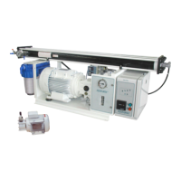
In the basic version, desalinator ESB is made up of the following elements:
REP. DESCRIPTION FUNCTION
EdM Hull fitting Always immerse in seawater, it ensures continuous seawater feeding of the unit. Not included in the
supplies.
Do not take water from the motor’s cooling system. Place the hull valve (V0) as far away as possible from
the rejected brine hull fitting (R).
V0 Hull valve Situated near the hull fitting, it ensures the closing of the seawater intake. Not included in the supplies.
A1/A2/A3
/B1/B2
Feeding pipes Ensures water supply to the unit through the filter (4). Imperative internal diameter must be 20
(Embedded steel spirale reinforcement A1/A2/A3) and internal diameter must be 19 (B1/B2).
1 Inlet valve Manual 3-way valve ensuring water supply to the unit, either with seawater in normal operation, or with
the water or chemical solution contained in a bucket during rinsing, cleaning or preservation of the
membrane.
2 Sea Strainer Small screen filter ensuring seawater filtering of large particles to protect the booster pump (LP).
3 Low Pressure Pump Driven by an electric motor, it raises seawater pressure to the required value between 5 / 10bar. Must be
installed 200mm below the water line.
4 5 µ filter Contains a filter cartridge ensuring seawater filtering of particles greater than 5µ (essential before water
enters the membrane).
5 LP Pressure Gauge Indicates the LP pressure.
6 Hydraulic amplifier Increases seawater pressure to produce fresh water through the R/O membrane.
7 Air bleed valve To bleed the system at the first start-up, or after replacement of the filters. Allows operation of the unit at
low pressure when opened for cleaning or preservation operations
8 Check valve Allows discharging the excess high pressure when modification operating parameters (setting at 68 bar).
9 HP Pressure Gauge Indicates the HP pressure.
10 R/O module Made up of pressure-resistant vessels, containing the membrane in which the desalination of seawater is
carried out.
11 Cleaning valve By opening this valve, the valve (1) itself being turned to cleaning position, the unit can be operated in
closed circuit on an auxiliary tank (or bucket) containing cleaning solution.
12 Production valve Manual 3-way valve that routes fresh water produced to the water-tank (hose F) or rejects it to the sea
(through hose C).
B3 Reject piping Collects the concentrated brine produced by the membrane for discharge to the sea. Imperative internal
diameter must be 19.
R Hull fitting Situated above the water line, ensures brine discharge to the sea. Not included in the supplies (avoid
installing the reject fitting in front of the seawater entry hull fitting).
A3/B4 Rinsing/Cleaning/
Preservation pipes
Ensures supply of fresh water and chemical solutions stored in a bucket or a holding tank, during
membrane rinsing, cleaning and preservation operations. Imperative internal diameter must be 20
(Embedded steel spirale reinforcement (A3)) and internal diameter must be 19 (B4).