MPS
Table of contents
Table of contentsTable of contents
Table of contents
1. Preface.........................................................................................4
1.1. The mps product family.................................................................4
2. Safety precautions.........................................................................4
3. Scope of delivery..........................................................................4
3.1. Flow sensor mps flow 100/200/400 (art. 53130, 53131, 53132).....4
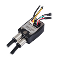
3.2. Flow sensor „high flow USB“ (art. 53129)........................................5
3.3. Pressure sensor mps pressure ∆40/∆100/∆500/1000/∆1000 (art.
53133, 53134, 53135, 53136, 53160)........................................5
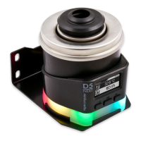
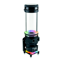
3.4. D5 pump motor with USB and aquabus interface (art. 41093)...........5
4. Flow sensor mps flow 100/200/400..............................................5
4.1. Technology and specific characteristics...........................................5
4.2. Stainless steel diffusor plate............................................................5
4.3. Installation of the diffusor plate.......................................................6
4.4. Integration into the cooling loop.....................................................6
5. Flow sensor „high flow USB“..........................................................7
5.1. Technology and specific characteristics...........................................7
5.2. Integration into the cooling loop.....................................................7
6. Pressure sensor mps pressure ∆40/∆100/∆500/1000/ ∆1000........7
6.1. Technology and specific characteristics...........................................7
6.2. Installation of fittings.....................................................................7
6.3. Installation as a fill level sensor.......................................................8
6.4. Installation as a differential pressure sensor.....................................8
7. D5 pump motor with USB and aquabus interface............................9
7.1. Description...................................................................................9
7.2. Installation to Aqua Computer products..........................................9
7.3. Allowed mounting orientations:......................................................9
7.4. Power connection and initial operation............................................9
7.5. Approved coolants......................................................................10
8. Electrical connectors...................................................................10
8.1. Connector „USB“........................................................................10
8.2. Connector „aquabus“.................................................................10
8.3. Connector „alarm“.....................................................................11
8.4. Connector „temp“.......................................................................11
9. aquasuite software......................................................................11
9.1. Installation of the aquasuite software.............................................12
9.2. Basic operation..........................................................................12
9.3. Symbols in the headlines..............................................................12
10. Overview pages (aquasuite).......................................................13
10.1. Desktop mode..........................................................................13
10.2. Creating new overview pages and activating edit mode................13
- 2 - Aqua Computer GmbH & Co. KG © 2012-2016
Gelliehäuser Str. 1, 37130 Gleichen