Do you have a question about the Aqua Select 832402B and is the answer not in the manual?
Lists necessary tools for assembling the Aqua Select Everest Step and related components.
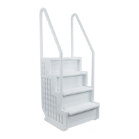
Illustrates and lists all primary parts and hardware for the Aqua Select Everest Step.
Provides a detailed list of numbered parts, models, descriptions, and quantities for assembly.
Attaching steps to one side panel using dowels, risers, and ensuring correct orientation.
Inserting risers between steps and positioning for optional light installation.
Attaching the second side panel to the assembled steps and risers.
Securing the step assembly using lock caps and a rubber mallet or hammer.
Positioning and securing the step bases to the side panels using zip ties.
Adding sand to the step for stability and proper seating in the pool.
Placing the step in the pool and ensuring water/air escape for stability.
Installing long handrail posts into the back of the step assembly.
Attaching mounting brackets to the deck to secure the step assembly.
Attaching handrails to posts and applying danger warning stickers.
Guidelines for lifting, intended use, and maximum weight capacity of the step.
Recommendations for step maintenance and proper storage during winter.
Routing low voltage wires from the light to the controller and transformer.
Connecting and operating the Step Bright controller for manual or automatic light control.
The Aqua Select® Everest Above-Ground Pool Step, model 832402B, is a robust and versatile entry system designed for above-ground and semi-inground pools with flat bottoms. It is suitable for pool wall heights and pool decks of 48", 52", and 54". The step is designed to accommodate one person at a time and has a maximum weight capacity of 350 lbs. It is crucial to adhere to this weight limit, as exceeding it can lead to step failure and potential injury.
The primary function of the Aqua Select® Everest Step is to provide a safe and convenient means of entry and exit for above-ground pools. It can be configured in several ways to suit different pool setups: as a standalone step with a flip-up outside ladder (model 832401BK), as part of a gated entry system with an in-pool ladder (model 832406EV), or as a component of a bridge system (model 832421B). Each configuration requires specific additional cartons and instructions, which are detailed in the manual.
Key components of the step include four steps (832402BS), four risers (AC RISERS), two side panels (AC PANELS), two bases (AC BASE), and various hardware for assembly. The step also includes two long handrail posts (AC LONGPOS), two short handrail posts (AC SHORTPOS), two handrails (832402SR), and two mounting brackets (832402MB) for securing the step to a deck. Sixteen lock caps (832402LC) are provided to secure the step components. For safety, two danger stickers (AC DNGRSTIK) are included to be placed on the handrails, one facing inside the pool and one facing outside.
A notable usage feature is the optional Step Bright Light (AC 08478), which provides illumination for the step. This light system includes a controller that allows for either manual or automatic operation. The low voltage wire from the light connects to the controller, which in turn connects to a transformer cable. The control pad for the light can be mounted on the side of an existing deck or post outside the pool. For bridge entry systems, the control can be installed on the outside step. The controller features "POWER ON," "LIGHT OK," and "PHOTO SENSOR" indicators. In manual mode, the "LIGHT OK" indicator illuminates, while in automatic mode, the "PHOTO SENSOR" indicator illuminates, allowing the light to turn on at sunset and off at dusk.
Assembly of the step involves several stages. First, the steps are connected to one of the side panels, ensuring the treads face the top of the panel and the riser grooves face the back. Risers are then inserted between the steps, with a designated position for the Step Bright Riser if the light system is being installed. Once all risers are in place, the second side panel is attached, locking the components together. Lock caps are then used to secure the pins sticking through the side panels. Two bases are attached to the bottom of the side panels using zip ties, ensuring the locking tab of the zip tie does not contact the pool liner to prevent damage.
An important technical specification and usage feature is the requirement for weighting the step. Approximately 50 lbs of sand (sold separately) are needed to ensure the step sits properly in the pool. The sand is poured into openings on the top step of each side panel, with 25 lbs per side. Rocking the step back and forth helps distribute the sand evenly.
When placing the assembled step into the pool, it is recommended that two people lift it to avoid injury. The pool filter should be turned off to stop water circulation. Once in the pool, the step should be tipped forward and moved left and right to allow air to escape and water to enter the steps and risers, which helps keep the step stationary. It is also recommended to install a step mat underneath the step to protect the pool liner; this item is sold separately.
For installations involving a deck, the long handrail posts are installed at the back of the step and secured with screws. Mounting brackets are then slid over the handrail posts and adjusted to be even with the deck. These brackets are screwed into the deck, although the specific screws are not included due to variations in deck materials. It is critical that the step is secured to the deck to prevent rocking or tipping. If the mounting brackets do not reach the deck, the deck surface must be extended.
The handrails are attached to the handrail posts after lubricating the inside of the posts with liquid soap or lubricant. The more curved part of the handrail is designed for the long handrail post. Screws are used to secure the handrails in place, and the danger stickers are applied.
Safety is paramount with this device. Users are reminded to face the ladder at all times when entering or exiting the pool. It is crucial not to jump or dive from the step due to shallow water. Children must be watched at all times. The ladder should be removed and secured when the pool is not occupied. Users are warned not to swim through, behind, or around the ladder to prevent entrapment or drowning.
Maintenance features include the recommendation to remove the step/ladder/bridges for winter to prevent cracking. Before storing, it is advised to spray down the step with hose water to rinse off any chemical residue. For storage, the step should be protected from the elements, either in a shed or garage, or covered with a tarp.
The manual also outlines the tools required for assembly: a small rubber mallet or hammer with a piece of wood, a Phillips head screwdriver, pliers, liquid soap or lubricant, 40 lbs of sand (sold separately), and a funnel.
| Brand | Aqua Select |
|---|---|
| Model | 832402B |
| Category | Ladders |
| Language | English |