FL7006/FL7030/FL7218/FL7040/FL7060Kit
ii
4. MAINTENANCE ............................................................................................... 33
4.1 General ................................................................................................................. 33
4.2 Safety Warning ..................................................................................................... 33
4.3 Unauthorized Repairs ........................................................................................... 33
4.4 Preventive Maintenance ....................................................................................... 33
4.4.1 Probe..................................................................................................................... 33
4.4.2 Cables ................................................................................................................... 34
4.4.3 Probe Interface ..................................................................................................... 34
4.5 Return Procedure .................................................................................................. 34
4.6 Periodic Calibration .............................................................................................. 34
4.7 Upgrade Policies .................................................................................................. 35
Appendix A: Guidance for Orienting Stalk Type Field Probes ............................... 37
Appendix B: Dimensional Drawings ........................................................................... 39
FIGURES
1-1 FL7006 or FL7030 ................................................................................................. 1
1-2 FL7218/FL7040/ FL7060 ....................................................................................... 1
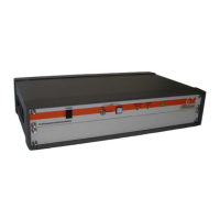
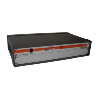
1-3 FI7000 Interface ..................................................................................................... 1
3-1 FL7006 and FL7030 Probe Features .................................................................... 18
3-2 FL7218/FL7040/FL7060 Probe Features ............................................................. 19
3-3 Interface Assembly Front Panel Features ............................................................. 20
3-4 Probe Interface Assembly Rear Panel Features .................................................... 20
3-5 Interface Assembly Label Details ....................................................................... 21
TABLES
3-1 FL7006 and FL7030 Probe Features .................................................................... 18
3-2 FL7218/FL7040/ FL7060 Probe Features ............................................................ 19
3-3 Interface Assembly Front Panel Features ............................................................. 20
3-4 Probe Interface Assembly Rear Panel Features .................................................... 20
3-5 Interface Assembly Label Details ........................................................................ 21
3-6 IEEE-488 Address Selection ................................................................................ 30