Rev J 1
1. INTRODUCTION
This manual provides operating, interfacing and selected service information pertinent to AR FL Series
Electric Field Probe Kits; Models FL7006, FL7030, FL7218, FL7040 and FL7060. The FL7006 and FL7030
probes incorporate proprietary and patented sensor design. All models use miniaturized probe electronics to
offer electric field probes for CW (continuous wave) electric field measurements.
1.1 PROBE KIT DESCRIPTION
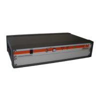
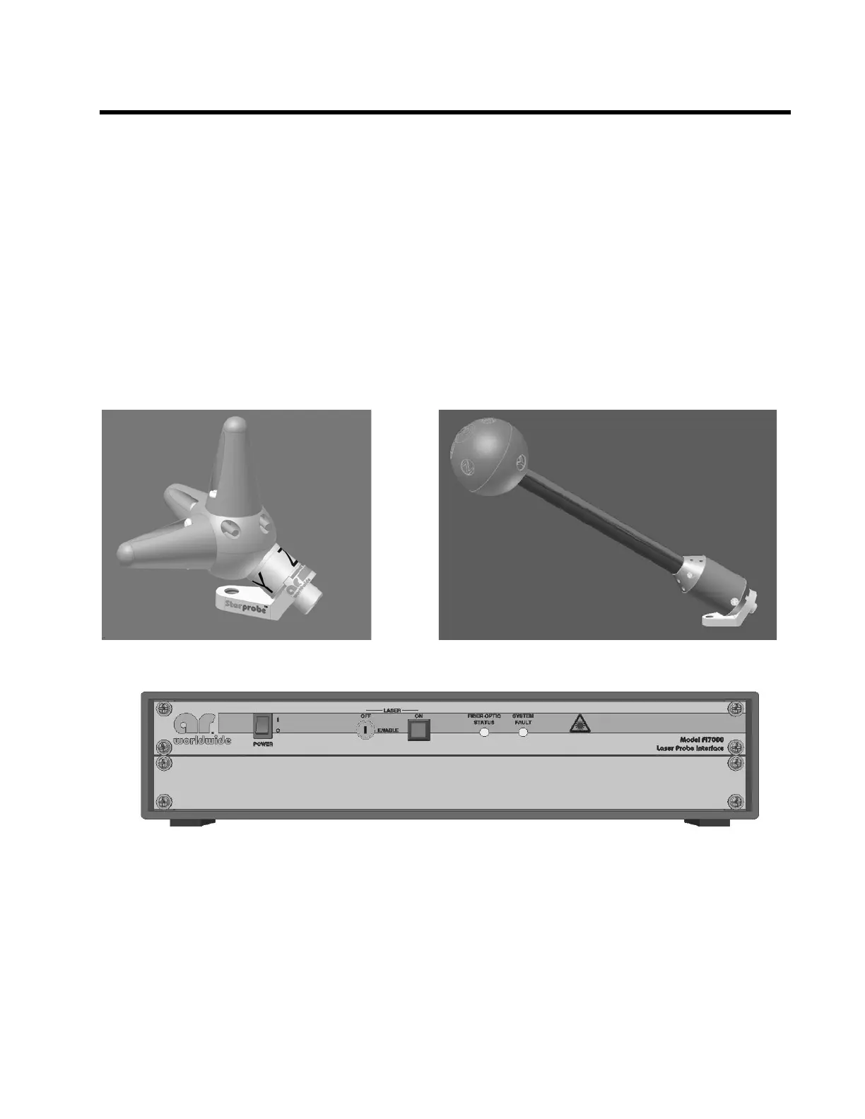
The Laser Probe Kit includes a FL7006 or FL7030 Probe (Figure 1-1) or FL7218/FL7040/FL7060 Probe
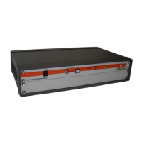
(Figure 1-2) and an FI7000 Interface (Figure 1-3). The probe communicates to its dedicated interface via
supplied fiber optic cables and bulkhead feed through adapters. The interface provides standard
communication protocols (RS-232, GPIB, USB 2.0) to the user’s host computer to relay the measured field
value. Field values relayed to the host may be further processed and/or displayed depending upon the host
application program (software). Each Probe Kit comes with a carrying case to house all parts except the
interface.
Figure 1-1. FL7006 or FL7030 Probe
Figure 1-2. FL7218/FL7040/FL7060 Probe
Figure 1-3. FI7000 Interface
1.2 SUGGESTED APPLICATIONS
• EMC field monitoring
• Electric field mapping
1.3 SPECIFICATIONS
Refer to the AR Specification sheets at the end of this section for detailed specifications of the kit, probe, and
interface.